[level-membership-for-anesthesiology-category]
Artifacts and Pitfalls
Christopher J. Gallagher and Gian Paparcuri
When you are in the OR, you are forever asking yourself, “Is it real, or is it Memorex?”. We get seduced by the great images, and you have to shake yourself and say, “This is not a REAL LIVE picture, this is an ULTRASOUND CREATION OF A PICTURE, and ultrasound can fool you”.
Artifacts change their appearance and appear or disappear depending on the view.
Real structures will remain constant and can be seen in multiple views.


 Interfere with image interpretation.
 Reflections not representing true anatomy.
 Part of an image will not represent the anatomic structure (reality) accurately


(See also CFD artifacts, pitfalls, and masses.)
Acoustic imaging assumptions (to assign the location and intensity of received echoes):
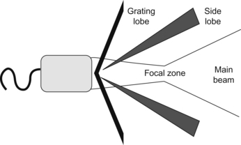
 Reflections arise only from structures along the beam’s main axis. Echoes detected originated from within the main ultrasound beam. Problem: side lobes, grating lobes.
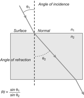
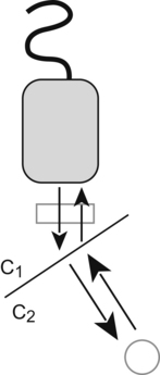
 Sound travels directly to a reflector and back (straight line). Problem: refraction.
 Echo returns to transducer after a single reflection. Problem: mirror images, reverberations.
 Sound (sound beam and its echo) travels in a straight line.


 Reflection’s intensity (strength) is related to tissue characteristics. Problem: attenuation.

 Acoustic energy in an ultrasound field is uniformly attenuated.
Artifacts
 Artifacts associated with US beam characteristics (beam width, side lobe, grating lobe, edge shadow).


Artifacts Associated with US Beam Characteristics
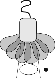
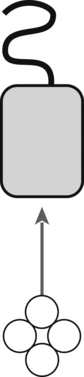
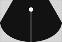
US beam exits transducer as a complex 3-D bowtie shape (below figure) with additional off-axis low-energy beams (side lobes and grating lobes). Strong reflector (highly reflective object) located outside the main US beam (peripheral field) may generate detectable echoes that will be displayed as having originated from within the main beam. Misplaced echoes overlapping anechoic structure. Adjust focal zone to the level of interest and place transducer at the center of the object of interest.
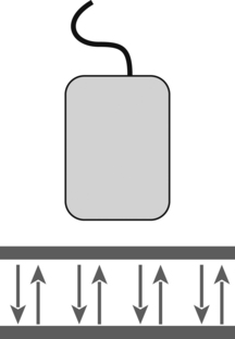
Beam width: distal beam (widened beam) widens beyond the actual transducer width (below figures).
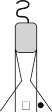
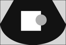
If the beam is oscillating rapidly, the multiple artifactual echos produced by the side lobes are displayed as a curved line at the same level as the true object.
Options: reduce power (below figures).

Artifacts Associated with Multiple Echoes
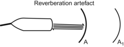
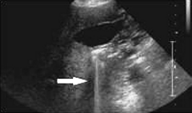
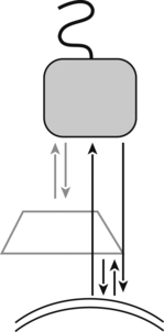
Reverberation artifact: echo signal returning to the transducer is reflected back to the tissues by the surface of the transducer or a dense object (two strong reflectors lying in the line, along the main axis of the ultrasound beam) creating multiple unreal superimposed images, equally spaced, ladder-like appearance at ever increasing depth. Pulse bounces back and forth between the two reflectors, sending multiple echoes back to the transducer. The first two echoes arise from true anatomic structures in their correct position. Example: PAC, calcified aorta (strong reflectors), makes sound wave ricochets (rebounding) back and forth between transducer and structure. Readjust the angle; reducing gain or the contrast might not eliminate ‘em.

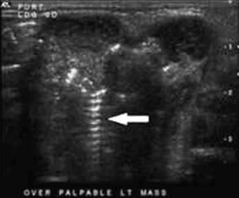
Linear reverberation: ascending aorta, mimics dissections.
Artifacts Associated with Velocity Errors
 Transmission angle/incident angle = propagation speed medium 2/medium 1 (when propagation speed in medium 2 is greater, the transmission angle is greater than the incident angle).
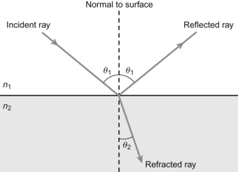
θ1 (incidence angle) > θ2 (transmission angle) because n1 > n2
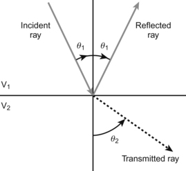
θ1 (incidence angle) < θ2 (transmission angle) because V1 < V2

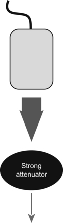
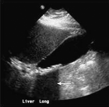
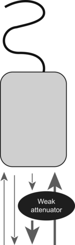
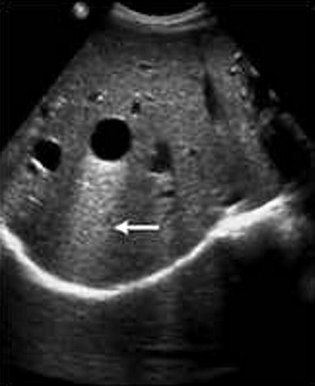
Artifacts Associated with Attenuation Errors
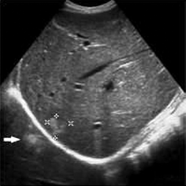
Thus when US beam encounters a strongly attenuating or highly reflective structure (structure with high attenuation), the amplitude of the beam distal to this structure is diminished (ultrasound beam is weakened), the echo returning from structures beyond (deeper) the highly attenuating structure will also be diminished, weakened (dark or hypoechoic band), resulting in poor resolution within the shadow.
Electronic interface: linear “dot” artifact affecting the whole image (electrocautery).
Range ambiguity: At high pulse repetition frequency (don’t be afraid to go back and look at the physics in Chapter 5 again), the ultrasound can get fooled into thinking an object is in the wrong location. A second pulse is sent out before the first one comes back, so the machine can’t tell where the signal came from.
Doppler Artifacts and Pitfalls
As before, don’t be afraid to go through the physics in Chapter 5 again. You finished physics a looooooooooooooooooooooooong time ago, and this stuff can be a little tricky.
Aliasing: you can’t measure a maximum velocity.
If the angle is more than 20 degrees off kilter, your Doppler will be inaccurate.
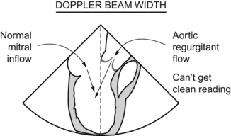
Beam width: this is the “Doppler equivalent” of the problem with side lobes. You are trying to see, for example, the left ventricular inflow from the left atrium, but your beam width is too wide and you also see an aortic regurgitant jet at the same time, screwing up the signal.
Structures Mimicking Pathology
This is total Visual City, USA, and a lot of it you’ve heard of before.
Nodulus arantii: kick ass name, huh?
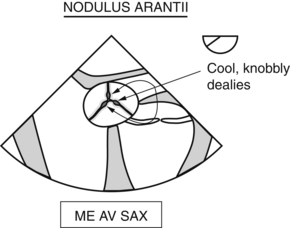
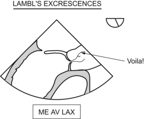
Filamentous thingamabobs attached (usually) to the aortic side of the aortic valve leaflets.
I already drew this once, don’t get greedy.
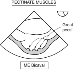
Pectinate muscles: parallel ridges along endocardial surfaces of the left and right atria, as well as both appendages.
Both of these were drawn a while ago. Re-read the book, if you missed it.
Chiari network: kind of like a Lambl’s excrescence in the atrium.
Epicardial pacing can make the septal wall appear hypokinetic or dyskinetic. The normal sequence of depolarization doesn’t occur, so you could be fooled into thinking there was a coronary occlusion leading to this regional wall motion abnormality.
[/level-membership-for-anesthesiology-category][not-level-membership-for-anesthesiology-category]
Artifacts and Pitfalls
Christopher J. Gallagher and Gian Paparcuri
When you are in the OR, you are forever asking yourself, “Is it real, or is it Memorex?”. We get seduced by the great images, and you have to shake yourself and say, “This is not a REAL LIVE picture, this is an ULTRASOUND CREATION OF A PICTURE, and ultrasound can fool you”.
Artifacts change their appearance and appear or disappear depending on the view.
Real structures will remain constant and can be seen in multiple views.
Interfere with image interpretation.
Reflections not representing true anatomy.
Part of an image will not represent the anatomic structure (reality) accurately
(See also CFD artifacts, pitfalls, and masses.)
Acoustic imaging assumptions (to assign the location and intensity of received echoes):
Reflections arise only from structures along the beam’s main axis. Echoes detected originated from within the main ultrasound beam. Problem: side lobes, grating lobes.
Sound travels directly to a reflector and back (straight line). Problem: refraction.
Echo returns to transducer after a single reflection. Problem: mirror images, reverberations.
Sound (sound beam and its echo) travels in a straight line.
Reflection’s intensity (strength) is related to tissue characteristics. Problem: attenuation.
Acoustic energy in an ultrasound field is uniformly attenuated.
Artifacts
Artifacts associated with US beam characteristics (beam width, side lobe, grating lobe, edge shadow).
Artifacts Associated with US Beam Characteristics
US beam exits transducer as a complex 3-D bowtie shape (below figure) with additional off-axis low-energy beams (side lobes and grating lobes). Strong reflector (highly reflective object) located outside the main US beam (peripheral field) may generate detectable echoes that will be displayed as having originated from within the main beam. Misplaced echoes overlapping anechoic structure. Adjust focal zone to the level of interest and place transducer at the center of the object of interest.
Beam width: distal beam (widened beam) widens beyond the actual transducer width (below figures).
If the beam is oscillating rapidly, the multiple artifactual echos produced by the side lobes are displayed as a curved line at the same level as the true object.
Options: reduce power (below figures).
