CHAPTER 16 Arthroscopically Assisted Reduction and Percutaneous Fixation of Scaphoid Fractures Using a Simple External Targeting System
Rationale
Percutaneous screw fixation is recognized as an effective treatment of acute nondisplaced scaphoid fractures.1–9 These techniques result in rapid healing, with minimal complications. Displaced fractures have traditionally required open reduction. Several authors have reported good results in small case series using arthroscopic–assisted reduction of displaced fractures, but achieving reduction and stable fixation with these techniques can be challenging.10,11
Surgical Technique
Imaging
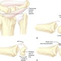
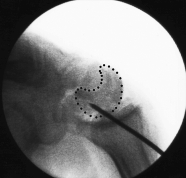
Scaphoid imaging includes locating the central scaphoid axis. This is accomplished by pronating the wrist until the scaphoid poles are aligned, and flexing the wrist approximately 45 degrees until the cylinder of the scaphoid becomes a circle (Figure 16.1). A perpendicular placed at the center of the circle represents the central axis of the scaphoid. This perpendicular is the longest distance a straight line can be placed through the scaphoid, the central scaphoid axis. Along the central axis, the longest screw can be placed without violating the scaphoid cartilage envelope. Biomechanically, the longest screw distributes and reduces the bending forces—which act to displace the scaphoid. Finally, clinical reports confirm that screws placed along the central axes achieve faster healing than those placed eccentrically.12
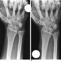
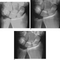
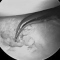
Scaphoid displacement can occur either as lateral displacement visualized on a posterior–anterior view as a step–off (Figure 16.2) or as forward flexion of the distal fragment on the proximal fragment displaying a V separation of the dorsal cortex on lateral or oblique views (Figure 16.3)—a future humpback deformity. On the PA view, this displacement appears as a foreshortened scaphoid. At the completion of this survey, two decisions must be made. First, is the scaphoid grossly aligned or not? Second, are there other injuries that need to be addressed?
Fracture Reduction and Guide–Wire Placement: A New Technique
Grossly Aligned Scaphoid
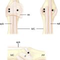
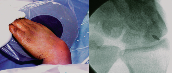
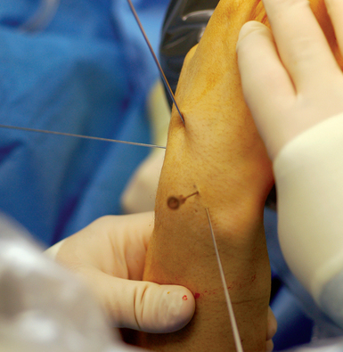
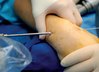
With minimal (<1 mm) or no displacement on imaging, the next step is to place a guide wire down the central scaphoid axis. For a variety of reasons, it might be difficult to visualize the central axis. A simple technique we now use is an “external cross K–wire scaphoid guide,” which permits external sighting of the distal scaphoid by percutaneously placed perpendicular K–wires. It does not require continuous imaging to drive the wire along the central axis. Imaging is only used to set up the targeting system. This guide requires the placement of two K–wires in the distal scaphoid in the same axial plane, perpendicular to the scaphoid and offset in a 90–degree arc. One wire is driven dorsal to volar in the PA plane of the distal scaphoid (Figure 16.4) and a second wire in the lateral scaphoid radial to ulnar (Figure 16.5).
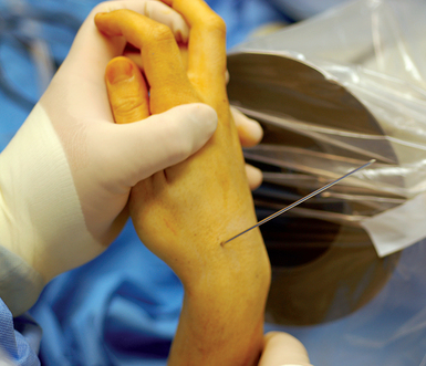
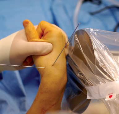
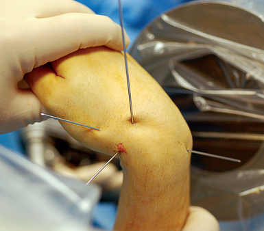
FIGURE 16.5 Second .062–inch targeting wire placed radial to ulnar in the midlateral position of the distal scaphoid.
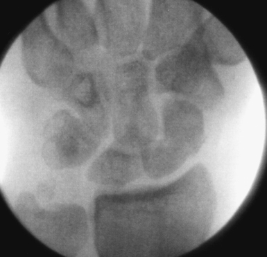
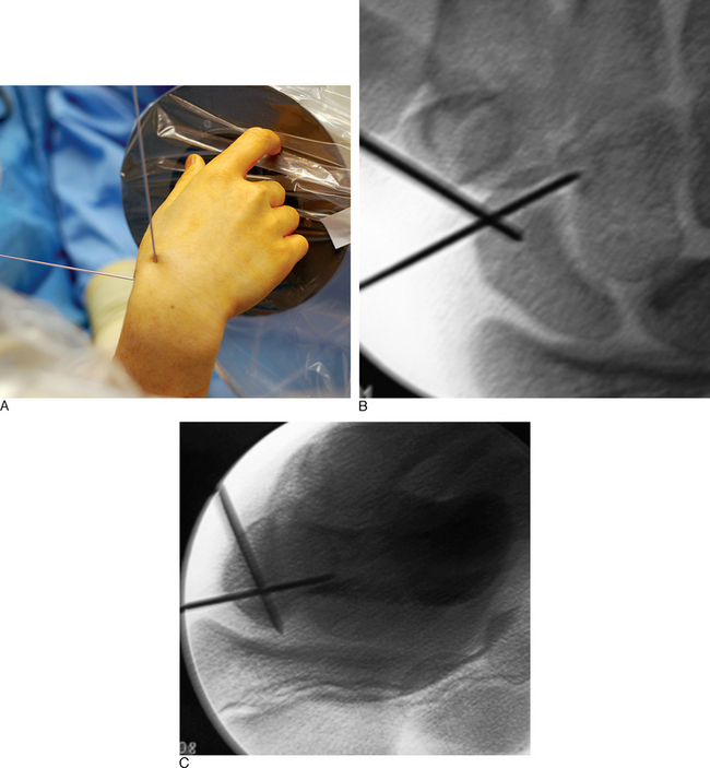
These wires cross at the distal scaphoid central axis and form a crosshair target for guide–wire placement (Figure 16.6a through c). To place the dorsal wire, the wrist must be ulnar deviated. This will extend the distal scaphoid fragment and will make the percutaneous perpendicular placement of the wire easier. With the wrist extended and ulna deviated, PA imaging of the dorsal scaphoid wire (if correctly perpendicular to the bone axis) will appear as a single dark point. The lateral radial wire is introduced also perpendicular to the distal scaphoid and driven toward and across the dorsal wire as it appears on image as a single point. A lateral fluroscopic image will confirm that the lateral wire has been placed in the mid–axis of the distal scaphoid.
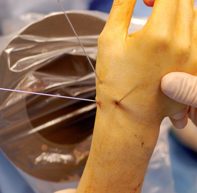
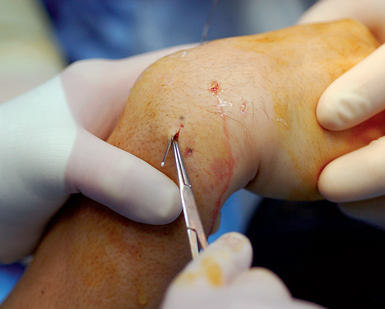
Next, the 3,4 arthroscopic portal is identified and marked using a 19–gauge needle (Figure 16.7a and b). The 3,4 arthroscopic portal is located 1 cm distal to Lister’s tubercle and can be easily imaged using a mini–fluoroscopic unit. This is the location of the proximal scaphoid pole and the starting point for the central axis guide wire to be driven from dorsal to volar in the flexed wrist.
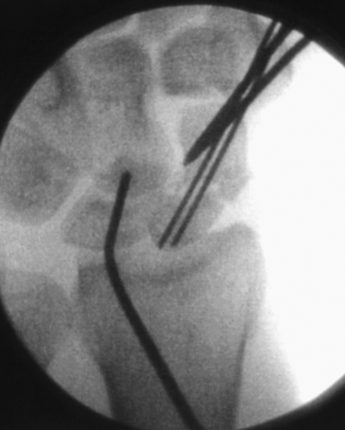
A .045–inch double–cut K–wire is placed in the 3–4 portal and impaled into the proximal scaphoid pole (Figure 16.8). Its position is confirmed fluoroscopically. Next, as the wire is driven toward the thumb base the direction is checked using the dorsal and radial guide wires (Figure 16.9). If the central axis guide wire is in the plane of both targeting wires, it will intersect the cross wires in the distal scaphoid in the central axis. This wire is usually driven through the trapezium because the scaphoid and trapezium are colinear. The wire is withdrawn volarly until the trailing end clears the radiocarpal joint, allowing the wrist to be extended (Figure 16.10).
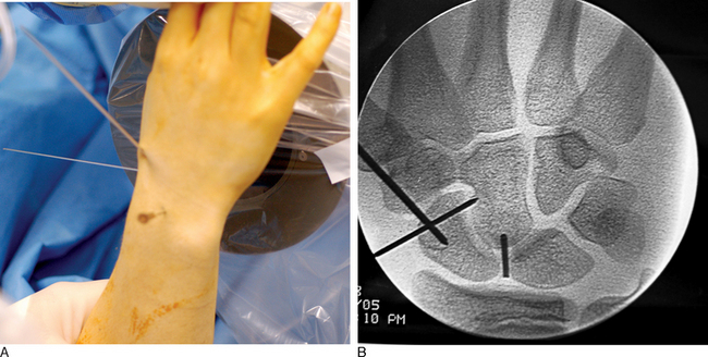
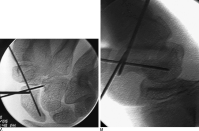
Imaging is now used to confirm the position of the wire and the scaphoid fracture alignment (Figure 16.11a and b). If satisfactory, the next step is an arthroscopic inspection of the joint. If placing the central axis scaphoid wire results in an incorrect path due to multiple incorrect passes, a correct path can be difficult to establish using a 0.045 wire. A stouter 0.062 wire, with its increased stiffness, can be used to establish the correct track. Once the correct path is established, the 0.062 wire can be exchanged for the 0.045 guide wire.
Grossly Displaced Scaphoid Fracture
To grossly align the scaphoid, the external cross K–wire scaphoid guide is assembled as described previously. Once the external cross K–wire scaphoid guide is assembled, a PA image is obtained and the fracture site is identified. A 19–gauge needle is inserted through the skin into the fracture site. The distal central scaphoid axis is identified. Because the distal scaphoid fracture fragment is commonly flexed (exposing the dorsal intramedullary canal of the scaphoid), a K–wire can easily be introduced into the fracture site and driven through the distal scaphoid intramedullary canal. The external cross K–wire scaphoid guide will provide direction as the wire is driven from dorsal to volar.
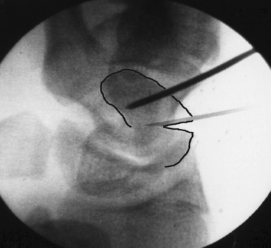
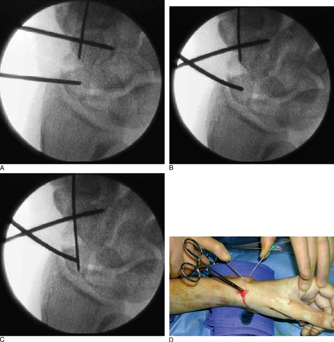
The position of the proximal fragment at this time is irrelevant, but will later be reduced. The wire is withdrawn volarly until the trailing edge of the wire is at the fracture site. Next, a .062 K–wire joystick is placed dorsal to volar into the proximal scaphoid fragment. With the wrist extended in a neutral position, the wrist is imaged as the two dorsal joysticks (one in the distal fragment and one in the proximal scaphoid fragment) are manipulated until fracture alignment is obtained (Figure 16.12a through d). The concave scaphoid surface is used as the key reference for fracture reduction. Fracture reduction is captured by driving the volar wire dorsally across the fracture site.
Once reduction and provisional fixation of the grossly displaced fracture has occurred, the next step is placement of the central axis scaphoid guide wire (as described previously). This wire will provide direction for both scaphoid reaming and screw implantation. With the wrist partially flexed, a mini–fluroscopic unit is used to locate the proximal scaphoid pole at the scapholunate interosseous ligament. This is the starting point for the central axis scaphoid guide wire, which will be driven from dorsal to volar with the wrist flexed. As the central axis wire is driven toward the thumb base, its direction is corrected using the external distal scaphoid K–wires (the dorsal wire provides radial ulna guidance and the lateral K–wire provides dorsal/volar orientation).
A successfully placed central axis scaphoid wire will hit the crossing wires in the distal scaphoid, the location of the central axis. The wire is driven volarly past this intersection, through the trapezium, and exits at the thumb base in a zone devoid of neurovascular structures. The wire is withdrawn until the trailing edge crosses the radiocarpal joint and the wrist can be safely extended without bending the wire. There are now two K–wires down the length of the scaphoid: one used to capture the initial reduction and the second placed down the long axis (Figure 16.13). The use of two K–wires limits bending forces and acts as an anti–rotation construct during scaphoid reaming and screw placement. Imaging is now used to confirm the position of the wire and the scaphoid fracture alignment. If satisfactory, the next step is an arthroscopic inspection of the joint.
If a DISI deformity is present due to extreme scaphoid flexion at the fracture site, fracture reduction can be achieved by hyperflexion of the wrist until the lunate is in a neutral position and a wire is driven through the distal radius into the lunate—securing it provisionally in a neutral position. Alternatively, the wire can be placed dorsal directly into the lunate in a neutral position. As long as an intact scapholunate interosseous ligament exists, the reduction force is transferred from the lunate to the scaphoid (Figure 16.14).
Arthroscopy
With the patient in a supine position, the arm is exsanguinated, the elbow is flexed, and the wrist is positioned upright in a spring–scale–driven traction tower. Twelve pounds of traction is distributed between four finger traps to reduce the possibility of a traction injury. A fluoroscopy unit is placed horizontal to the floor and perpendicular to the wrist as the radiocarpal and midcarpal joints are identified with imaging. Nineteen–gauge needles are introduced into the wrist joint to identify the radiocarpal and midcarpal portals. This maneuver limits iatrogenic injury to the joint, which can result from multiple attempts to introduce a blunt trocar blindly.
With arthroscopy, the sulcus (which defines the scapholunate ligament) can be identified and probed. With partial tears, the probe will be visualized by the arthroscope in the midcarpal portal as it passes from the radiocarpal joint into the midcarpal joint through a tear in the SLIO (scapholunate interosseous) ligament. Any carpal ligament injuries detected are graded using the Geissler grading system.13 Grade I and II ligament injuries are treated with debridement and shrinkage alone. Grade III injuries are treated with debridement, and after fracture repair carpal pinning for six weeks. Grade IV ligament injuries require open repair of the dorsal SLIO ligament with bone anchors and carpal pinning. The need for the addition of a dorsal capsulodesis tether is determined by the quality of the acute repair after scaphoid fixation. Tears of the triangular fibrocartilage complex are classified using the Palmer classification and treated accordingly.14
Scaphoid Length
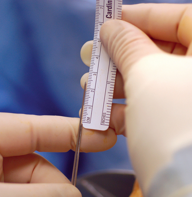
At completion of arthroscopy, with fracture reduction and guide–wire position confirmed, the screw size must now be selected. To accomplish this, the scaphoid length must be determined. The wrist is flexed and the central axis scaphoid guide wire at the base of the thumb is driven dorsally. The wire is adjusted until the trailing end is in the subchondral bone of the distal scaphoid pole. A second wire of equal length is placed percutaneously at the proximal scaphoid pole and parallel to the guide wire. The difference in length between the trailing end of each wire is the scaphoid length (Figure 16.15).
The screw length selected should be 4 mm less than the scaphoid length. This permits 2 mm of clearance of the screw at each end of the scaphoid, thus ensuring complete implantation without screw exposure. The most common reported complication of percutaneous screw scaphoid fixation is implantation of a screw that is too long.2
Rigid Fixation with Headless Cannulated Screw
Once the scaphoid is correctly aligned and its length has been determined, with the wrist maintained in a flexed position the central axis guide wire is adjusted so that its ends are equally exposed between the dorsal wrist and volar radial thumb. This prevents the wire from becoming dislodged during bone reaming and screw implantation (Figure 16.16). It is critical that the wrist maintains a flexed position to prevent the wire from bending. Otherwise, drilling and screw placement will be difficult.
Dorsal implantation of a headless compression screw is recommended for scaphoid fractures of the proximal pole and volar implantation for distal pole fractures because this permits maximum fracture compression. Fractures of the waist may be fixed from a dorsal or volar approach as long as the screw is implanted along the central scaphoid axis. Volar implantation often requires reaming through the trapezium, because this is the central axis. Our experience has been that smooth holes in articular surfaces heal without difficulty. Blunt dissection along the guide wire exposes a tract to the dorsal wrist capsule and scaphoid base (Figure 16.17).
The scaphoid is prepared by drilling a path 2 mm short of the opposite scaphoid cortex with a cannulated hand drill. Newer self–drilling screws have reduced the need for extensive drilling, but drilling of the scaphoid should include at least several millimeters across the fracture site—the concern being that in young bone with increased bone density as the screw crosses the fracture site the screw may be unable to cut and penetrate the opposite bone fragment and force fracture separation (even with self–drilling screws).
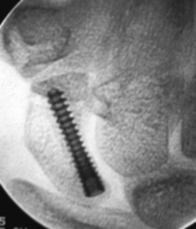
The implantation of a headless screw 4 mm shorter greatly reduces the chance that the screw will penetrate the scaphoid cartilage envelope. It is critical to use fluoroscopy to check the position and depth of the drill during reaming. The scaphoid should never be reamed to the opposite bone cortex (over–drilling). This reduces fracture compression and increases the risk of motion at the fracture site. A standard Acutrak screw is advanced under fluoroscopic guidance down the central scaphoid axis to within 1 to 2 mm of the opposite cortex (Figure 16.18). If the screw is advanced to the distal cortex, attempts to advance the screw further will force the fracture fragments to gap and separate.
Postoperative Care and Scaphoid Healing
Standard radiographs at three months have been demonstrated to be unreliable in determining scaphoid healing.15 It is important to understand that patients are often pain free prior to CT evidence of healing. Contact sports and heavy labor are restricted until fracture healing is confirmed by CT. If bridging bone is not identified by 12 weeks, one must consider aggressive treatment (including percutaneous bone grafting). Delay in treatment for early nonunions delays healing. We do not routinely cast our scaphoid fractures postoperatively, but candidates for additional protection are evaluated on a case–by–case basis.
1 Adolfsson L, Lindau T, Arner M. Acutrak screw fixation versus cast immobilisation for undisplaced scaphoid waist fractures. J Hand Surg [Br]. 2001;26(3):192-195.
2 Bond CD, Shin AY, McBride MT, et al. Percutaneous screw fixation or cast immobilization for nondisplaced scaphoid fractures. J Bone Joint Surg [Am]. 2001;83-A(4):483-488.
3 Haddad FS, Goddard NJ. Acute percutaneous scaphoid fixation: A pilot study. J Bone Joint Surg [Br]. 1998;80(1):95-99.
4 Inoue G, Shionoya K. Herbert screw fixation by limited access for acute fractures of the scaphoid. J Bone Joint Surg [Br]. 1997;79(3):418-421.
5 Ledoux P, Chahidi N, Moermans JP, Kinnen L. Percutaneous Herbert screw osteosynthesis of the scaphoid bone. Acta Orthop Belg. 1995;61(1):43-47.
6 Taras JS, Sweet S, Shum W, Weiss LE, Bartolozzi A. Percutaneous and arthroscopic screw fixation of scaphoid fractures in the athlete. Hand Clinics. 1999;15(3):467-473.
7 Slade JFIII, Grauer JN, Mahoney JD. Arthroscopic reduction and percutaneous fixation of scaphoid fractures with a novel dorsal technique. Orthop Clin North Am. 2001;32(2):247-261.
8 Schadel-Hopfner M, Bohringer G, Gotzen L. Percutaneous osteosynthesis of scaphoid fracture with the Herbert-Whipple screw: Technique and results. Handchirurgie, Mikrochirurgie, Plastische Chirurgie. 2000;32(4):271-276.
9 Yip HS, Wu WC, Chang RY, So TY. Percutaneous cannulated screw fixation of acute scaphoid waist fracture. J Hand Surg [Br]. 2002;27(1):42-46.
10 Shih JT, Lee HM, Hou YT, Tan CM. Results of arthroscopic reduction and percutaneous fixation for acute displaced scaphoid fractures. Arthroscopy. 2005;21(5):620-626.
11 Slade JF, Merrell G, Lozano-Caldron S, Ring D: Arthroscopic Assisted, Percutaneous Reduction and Fixation of Displaced Scaphoid Fractures. Poster, ASSH Annual Meeting, September 2005.
12 Trumble TE, Gilbert M, Murray LW, Smith J, Rafijah G, McCallister WV. Displaced scaphoid fractures treated with open reduction and internal fixation with a cannulated screw. J Bone Joint Surg [Am]. 2000;82(5):633-641.
13 Geissler WB, Freeland AE, Savoie FH, McIntyre LW, Whipple TL. Intracarpal soft-tissue lesions associated with an intra-articular fracture of the distal end of the radius. J Bone Joint Surg [Am]. 1996;78(3):357-365.
14 Palmer AK. Triangular fibrocartilage complex lesions: A classification. J Hand Surg. 1989;14A:594-606.
15 Dias JJ. Definition of union after acute fracture and surgery for fracture nonunion of the scaphoid. J Hand Surg [Br]. 2001;26(4):321-325.