[level-membership-for-cardiovascular-category]
24 Approach to Pulse Generator Changes
Replacement of the pulse generator of a pacemaker or a defibrillator may occur at any time in the life of a patient with an implanted device. Although this need is most often the result of the finite life span of the battery, replacement of the device may also be precipitated by such diverse causes as infection,1–12 erosion,13–16 trauma,17–23 component failure,24–29 and migration of the device.30–34 In recent years, the need for system upgrade has become an increasingly important indication for pulse generator replacement and associated lead revision.35–43 This is the result of the increasing number of devices being implanted for newer indications in a broader patient population, the generally younger age at which patients receive implants, and patients living longer after device implantation because of advances in medical treatment as well as the device’s life sustaining effects. Indications for device replacement have evolved with the development of new technologies and greater understanding of cardiac physiology. These more recent requirements for replacement may involve upgrade of a pacemaker to a defibrillator, but more importantly and with greater complexity, upgrade to a biventricular cardiac resynchronization device through the addition of new leads, including a coronary sinus electrode44,45 (Box 24-1). Generator change may also be required secondarily from the need for lead replacement or revision,46–51 including lead advisories and recalls,52–57 especially if the generator is already near end of service. Chronic lead malfunction, in particular low lead impedance, may also require premature battery replacement because of high current drain.
Box 24-1
Indications for Pacemaker or ICD Generator Replacement
Because of the variety of indications for replacement of pacemaker or defibrillator generators, the approach to generator change or lead revision begins at the initial implantation of the system. Meticulous technique in the positioning of endocardial leads allows optimal programming of the pulse generator to reduce long-term battery drain, thereby prolonging the life of the generator.58 Careful lead positioning also reduces the likelihood of lead dislodgment that would require reoperation.49,50,59,60 Care with venous entry, lead fixation, lead-generator connection, pocket location, appropriate surgical plane, and handling of components enhances long-term pacing and sensing function. Ensuring that leads in the generator pocket are placed posterior to the pulse generator improves the likelihood of expeditious pulse generator replacement without lead damage. Bulkier defibrillator leads or lead headers may be placed in the same surgical plane next to the device instead of behind it. Ensuring that the pocket is of adequate size to accommodate easily the pulse generator and lead coils reduces the risk of damage to the leads in the pocket caused by excessive bending, which itself may result in lead fractures in a location separate from the anchoring sleeve, usually the most vulnerable area for lead breakage. Thus, the primary implanting physician prepares the stage for successful reoperation (Box 24-2).
Box 24-2
Factors to Reduce Need for Reoperation
 Special Considerations for Implantable Cardioverter-Defibrillators
Since the first surgical placement of an implantable cardioverter-defibrillator (ICD) in 1980,61 the role of ICDs in the management of patients with life-threatening ventricular tachyarrhythmias has become well established. Advanced indications have enabled widespread use of ICDs in clinical practice. Many patients outlive the life span of their first ICD generator. As with pacemakers, ICDs are prone to complications such as infection and malfunction, necessitating replacement or revision of the generator or leads. Although the approach to ICD generator change, lead evaluation, and reoperation can be extrapolated from the approach to pacemaker revision, certain aspects of ICD generator change and revision deserve special consideration. These include the need to upgrade to more complex lead systems or pacing modes (including cardiac resynchronization), lead malfunction in more complex lead systems that involve defibrillation as well as pacing, inadequate defibrillation thresholds, change of implantation site, and interchangeability of older devices and leads to newer models, or the interchangeability of components from various manufacturers. Each of these issues is addressed in this chapter in relation to special considerations for ICD devices.
 Patient Evaluation
Noninvasive Evaluation
Documentation of Pacemaker Pulse Generator Battery Depletion
Most bradycardia pacemaker pulse generators provide direct or indirect indicators of battery depletion, documenting the need for enhanced follow-up, elective generator replacement, or incipient battery failure (end of service). Additionally, certain nonspecific indicators may alert the physician to early signs of battery wear (Box 24-3). Because most pacemaker patients are followed by remote monitoring systems more frequently than by full evaluation in the physician’s office, it is not surprising that battery depletion for permanent pacemaker patients is most often detected through remote recordings.62–65 Remote evaluation of defibrillator systems also allows interrogation of device function and arrhythmic events, as well as battery capacity.66–73
A change in magnet-activated paced rate remains the most common indicator of reduced battery output voltage for pacemakers (Box 24-4). Some pacemaker pulse generator models respond to declining voltages through a gradual reduction in magnet-activated pacing rate; reduced rates indicate the need for enhanced follow-up, with even slower rates indicating elective or obligatory replacement. Other models demonstrate an abrupt shift in the magnet-activated paced rate at the enhanced follow-up period or at the time of elective replacement. A demand mode switch from DDD to VVI (or a magnet mode switch from DOO to VOO) may occur at the elective replacement time or as an obligate replacement indicator for dual-chamber systems before complete battery failure. Inability to reprogram the device, inaccurate measurement of lead impedances, and an automatically reprogrammed reduction in data storage capabilities to preserve battery life may also occur as the generator approaches end of service.
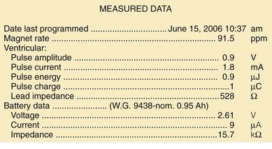
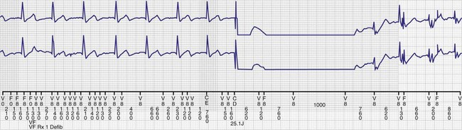
Other, secondary parameters suggest gradual battery depletion and can be interrogated remotely. The usual battery impedance in a new pulse generator is less than 1000 ohms (Ω). As pulse generator batteries deplete, internal battery impedance increases, providing a secondary indicator of the impending need for replacement (Fig. 24-1). Replacement is not required, however, until more definitive indicators appear, such as a change in magnet-activated pacing rate, a specific elective replacement indicator voltage, or mode switch. The patient’s dependence on the pacing functions of the device needs to be considered when timing the generator replacement. For example, a patient with complete heart block may not tolerate a mode switch to an asynchronous VVI pacing mode at the elective replacement time.
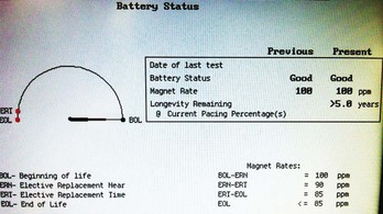
Telemetered battery depletion curves or battery status screens (Fig. 24-2), internal calculations of anticipated device longevity at current programmed settings, and a general knowledge of the expected performance of various generators all assist in anticipating a pacemaker generator’s end of service. Ultimately, loss of sensing and pacing capabilities occurs with battery exhaustion. The rate of battery depletion may accelerate as the device reaches end of service, making timely replacement in dependent patients very important.
Indicators for Replacement of ICD Generators
Some specific ICD models use battery voltage to produce labels that indicate the beginning, middle, or end of service for pulse generators. These labels can be obtained directly through interrogation of the device in the office. End of service may also be clearly indicated graphically (see Fig. 24-2).
Documentation of Lead Malfunction
A variety of causes of lead malfunction require reoperation,51–5774 from primary lead dysfunction to premature battery depletion as a result of excessive current drain (see Box 24-1). Primary lead malfunction may result from outer insulation break,75–81 inner insulation break in a bipolar coaxial lead,82,83 lead conductor fracture,17,19,84–86 or lead dislodgment.49,50,59,60,87 Current drain may be increased by (1) high pacing thresholds46,88–90 through a need to increase output voltage, (2) failure to optimize generator output for long-term pacing after lead maturation, or (3) inner insulation break with a resultant low pacing impedance. All these scenarios can result in premature battery depletion. Before reoperation for lead malfunction is performed in these patients with primary lead malfunction, the physician should consider upgrading or replacing the pulse generator, especially if the battery is old.
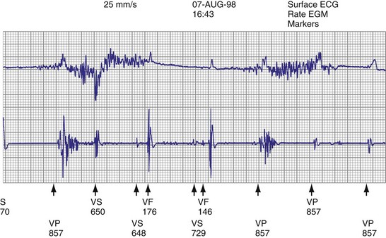
Lead malfunction can usually be documented by noninvasive telemetric evaluation or remote monitoring.63,66–73,91 A measured bipolar pacing lead impedance less than 200 Ω suggests an inner insulation break between the two coaxial pacing coils. An outer insulation break may be the result of lead wear or may have been inadvertently caused during surgery, especially with generator replacement; an inner insulation break between the two coils of a bipolar system occurs most often at the subclavian insertion site as the result of crush injury to the lead, especially with leads inserted into the subclavian vein and tied securely in a medial position in patients with a tight clavicular–first rib space. Telemetry for lead diagnostics may demonstrate markedly low bipolar pacing impedance in patients with an inner lead insulation break. The impedance may vary with manipulation of the pacemaker, which causes intermittent short-circuiting of the two lead conductors (Fig. 24-3).
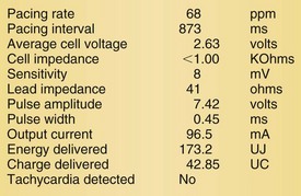
High pacing lead impedance (generally >1200 Ω) may be the result of lead conductor fracture or an incomplete circuit caused by a loose lead pin–pulse generator connection. Rarely, this may occur with fractures of conductors inside the pulse generator header. The introduction of high-impedance leads makes it essential to compare the impedance at implantation with follow-up impedance measurements and with established acceptable impedance ranges for each lead. Depending on the point of discontinuity, lead impedance may vary with manipulation of the pulse generator or with respiration. Lead conductor fractures may be evident on chest radiographs or fluoroscopy; however, absence of visual evidence does not exclude conductor fracture. A break in the connection of the lead to the generator, or within the lead itself, can produce intermittent loss of energy delivery to the heart, which in turn results in absence of pacemaker spikes. Undersensing, or oversensing caused by lead “chatter,” may also occur with lead conductor fracture (Fig. 24-4). Most recently, this scenario has occurred with a recalled high-energy ICD lead system.92
Special Issues for ICD Leads
The ICD lead remains the weak link in the ICD system. Oversensing caused by diaphragmatic impulses or extraneous signals may inhibit pacing therapy or lead to inappropriate delivery of “treatment” for presumed ventricular tachyarrhythmias that actually represent noise sensing.93,94 Further, although fracture and degradation of leads have become less common with transvenous (vs. epicardial) ICD lead systems, these problems nevertheless occur with some frequency, necessitating reprogramming or reoperation.95 Conductor fractures resulting from specific lead design issues have led to recalls and the need for reoperation in patients who experience a lead fracture92 (Fig. 24-5).
Measuring high-energy electrode impedance in early devices required delivery of a shock, either to treat a clinical tachyarrhythmia or as part of a noninvasive testing protocol. As a result, about 10% of patients undergoing ICD generator replacement because of battery depletion were found to have a previously undetected sensing or defibrillation system failure.96,97
Determination of Pulse Generator-Lead Interface Malfunction
Pulse generator–lead interface problems may be grouped into three categories: (1) loose, incomplete, or uninsulated connections; (2) reversal of atrial and ventricular leads in the pulse generator connector block (for ICDs, reversal of shocking electrode polarity may also occur); and (3) pulse generator–lead mismatch.98,99
Beyond ensuring the presence of adequate and appropriate lead connections to the pulse generator, the battery connector block and leads must be compatible (see later).98–102 This issue is less important with the standardization of new lead models used for device upgrades or generator replacements. However, incompatibility can result in fluid leakage or loose connections, with resultant loss of pace/sense or shocking capabilities, requiring reoperation.
Detection of Need for Reoperation for Other Reasons
Other indications for pacemaker or ICD generator replacement or lead revision generally become apparent through careful patient evaluation (see Box 24-1). Abrupt pulse generator failure with no antecedent sign of battery depletion is rare but can occur, producing symptoms in pacemaker-dependent patients. In others, abnormal pacing output or rate, lack of pacing output, or inappropriate sensing from generator malfunction may be detected by remote interrogation or in the office.27 Of particular importance to patients with ICDs are the risks of no output when required to terminate tachyarrhythmias, inappropriate shocks from oversensing of diaphragmatic or lead chatter artifact (see Fig. 24-5), and oversensing of extraneous electromagnetic signals, such as surveillance systems or high-voltage generators, which can be sensed as ventricular fibrillation or can inhibit ventricular pacing output. Cellular telephones rarely present substantial interference because of variations in signal frequency.103–106
Development of pacemaker syndrome in patients with implanted ventricular demand (VVI), ventricular rate-responsive (VVIR), or atrial rate-responsive (AAIR) pacemakers presents another indication for device revision. This need should be apparent from history and physical examination, although confirmatory blood pressure or cardiac output measurements may be required. Pacemaker syndrome occurring with an implanted functioning dual-chamber pacemaker with normal lead function must be managed by reprogramming.107–110
Interchangeability of Products from Different Manufacturers
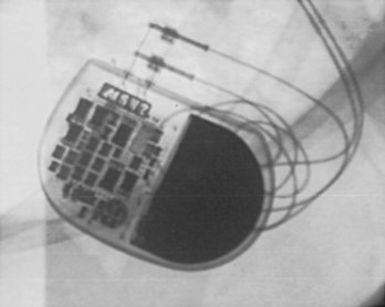
Early ICD leads from different manufacturers were compatible only with ICD pulse generators from the same manufacturer. This is especially evident when replacing generators that used LV-1 leads (Fig. 24-6). For later models, manufacturers have adhered to standard header designs for ICDs, including IS-1 ports for both atrial and ventricular pace/sense leads. Defibrillation ports now also follow a standard for defibrillation lead headers, DF-1, a 3.2-mm unipolar lead head with sealing rings (Fig. 24-7). The newest agreed-on IS-4 standard, which provides four electrical connections combining the functions of a bipolar pace/sense connection with up to two high-voltage connections, should reduce some of the confusion. However, there are two approved IS-4 connections with limited distribution at this time, one for devices with and one for devices without high-voltage (defibrillation) capacity. Eventually, this situation should simplify connections, except when extra leads for defibrillation are required in individual patients, which would require an adapter to connect to the IS-4 lead111 (Fig. 24-8).
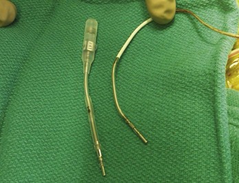
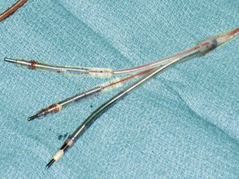
Figure 24-7 Typical trifurcated high-energy ICD lead header at generator replacement.
The most inferior electrode is the coaxial IS-1 standard bipolar rate/sense electrode, with the proximal and distal defibrillation (DF-1) standard electrodes above that, carrying red insulation over the high-energy wires (Boston Scientific). The structural integrity of the lead headers and the trifurcation can be readily examined at generator replacement. The bulk of the trifurcation and the three lead headers are replaced by a single lead head in the DF-4 configuration (see Fig. 24-8).
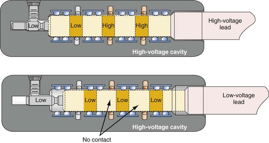
Figure 24-8 Schematics of quadripolar high-voltage and low-voltage lead pin configurations.
(From Proposed IS-4 Standard; American Association of Medical Instrumentation presentation at Cardiostim, Nice, France, 2004; and ISO Standard: Active implantable medical devices: four-pole connector system for implantable cardiac rhythm management devices—dimensional and test requirements. Geneva, 2009, International Standards Organization—E:\ISO FDIS 27186 (E) 25June2009.doc STD Version 2.1c2.)
Special Indications for Replacement of ICD Generators
As outlined in Box 24-1, the ICD generator may need to be replaced for other reasons, as discussed here.
Malfunction of Generator with or without Lead Malfunction
Hardware or software errors in the ICD generator, or more often malfunctioning ICD leads, may result in the need to revise the ICD system. The overall reported incidence of lead-related complications has ranged from 2% to 28%.112,113 These complications typically manifest as inappropriate shocks resulting from oversensing of noise; noise sensing from chatter caused by a fractured conductor has led to inappropriate shocks and pacing inhibition in some patients implanted with specific Medtronic high-energy electrodes (see Fig. 24-5). Alternatively, ineffective shocks caused by shunting of defibrillation energy from an inner insulator breach may lead to a low impedance route for high energy to be delivered directly back to the pulse generator and can cause pulse generator failure. Replacement of the ICD pulse generator may be indicated in each of these scenarios, in conjunction with lead revision or extraction, because of premature battery depletion, pulse generator failure, or to avoid another operation in the near future if the battery is already partially depleted.
Upgrading to Higher-Energy Device or Addition of Hardware for Inadequate Defibrillation Threshold
An elevated defibrillation threshold (DFT) detected through noninvasive testing or at elective generator replacement may require a change in hardware configuration. Options include placing a generator capable of delivering higher defibrillation energy to respond to an elevated DFT (although most current devices can do this), waveform adjustments,114 repositioning the right ventricular apical (RVA) shocking electrode, or the addition of various other lead systems, including superior vena cava or azygos vein coils, or subcutaneous coils, arrays, or patches to better distribute current around the heart to reduce the DFT,115–122 lowering shock electrode impedance for higher current delivery.
Reoperation may be required for antiarrhythmic drug changes that lead to substantial alterations in the DFT, although elimination of the offending medication provides a more straightforward solution.123,124 Also, the drug may be changed to an agent that lowers DFT, or a class III medication may be added to reduce DFT.125
Upgrade to Biventricular, Cardiac Resynchronization System
Upgrade to a biventricular (BiV) cardiac resynchronization system has become one of the most common indications for ICD reoperation, either as a de novo device upgrade or at the time of generator replacement.35–43126 Upgrade requires generator replacement and insertion of a new coronary sinus (CS)/LV electrode. We perform venography to ensure patency of the vasculature for the new lead if any difficulty is encountered in accessing the axillary vein. Understanding the venous anatomy is critical to making the correct surgical decision. If the subclavian/axillary venous system is occluded, options include lead extraction to produce a conduit or placing the CS lead on the opposite side and tunneling it across the chest to the pulse generator. Implantation of the new lead and device often requires a pocket revision to accommodate the larger generator. Surgical aspects for upgrade to a BiV system are addressed later.127–131
Complications of Pacemaker or ICD Implantation That Require Reoperation
Reoperation may be required for complications resulting from the initial implantation procedure.13,132–139 Indications include large pocket hematomas or effusions, cardiac chamber perforation by a lead, or a need to reposition the pulse generator. Most small to moderate hematomas resolve; the risk of secondarily introducing infection through reoperation or aspiration should be avoided as much as possible. Large hematomas or effusions that do not resolve and that compromise the blood supply through pressure on the overlying skin require evacuation followed by primary closure, because the pocket cannot be left open with a device in place.
Bolus dosing of heparin, use of enoxaparin, and large loading doses of warfarin should be avoided to reduce hematoma risk. We continue warfarin at full anticoagulant levels for all generator replacements and for lead revisions on patients in whom there is an increased risk of discontinuing anticoagulation.140
Pocket twitch (due to lead insulation break, loose lead-generator connection, or exposed set-screw), diaphragmatic pacing, or skeletal muscle stimulation or myopotential inhibition141 may require surgical intervention if such problems cannot be solved by reprogramming.
Identification of Pulse Generator Make and Model
The most straightforward means of identifying a pulse generator is to obtain information directly from the patient (Box 24-5). An identification card specifies the type of device, model and serial number, implantation date, name of implanting or monitoring physician, and lead model and serial numbers. This information may also be obtained from records from the manufacturer, implanting or monitoring physician, transtelephonic or remote service that monitors the patient, or institution where device was placed. If none of these is helpful, alternative methods must be used to identify the pulse generator. Identification of the make and model of the existing pulse generator is crucial to determining its true functional status and, with earlier leads, to have the necessary information to select a compatible replacement or upgraded device. In the rare case of a pulse generator that cannot be identified before surgery, the implanting physician must have a full array of leads, generators, and adapters available at reoperation.
Magnet Response
The response of a bradycardia pacemaker pulse generator to placement of a magnet can assist in the identification of its manufacturer (see Box 24-5). Pacemaker pulse generators respond to magnet application by entering a fixed-rate, single-chamber or dual-chamber pacing mode corresponding to the type of generator and the programmed mode. Magnet rates vary among manufacturers and may provide a clue to the origin of the device. To undergo a magnet-activated test, the patient must be connected to an electrocardiographic recorder before the magnet is applied and must remain connected until after the magnet is removed. The first few paced complexes after magnet application may occur at a rate or output other than that seen later in the recording, providing identification data as well as information regarding the integrity of the pulse generator and lead system; for example, the delivered pulse width may be reduced during the first few paced complexes to ensure that capture still occurs with an adequate safety margin, the “threshold margin test.” Furthermore, with constant magnet application over the pacemaker, some devices continue to pace at a fixed rate, whereas others cease pacing after a programmed number of intervals. Devices temporarily reprogrammed to a backup mode by electrical interference (e.g., electrocautery during surgery) may exhibit unusual magnet responses.
Radiographic or Fluoroscopic Identification of Pulse Generator
Pacemaker and ICD pulse generators can be identified from their appearance under radiography, the most helpful method for identifying unknown devices. The shape and size of the generator may characterize a particular manufacturer (e.g., square, oval, elongated ellipsoid, round), although pulse generator shape can vary significantly from one model to another, even in those by the same manufacturer. Considering that the life span of some pacemaker devices may exceed 10 or 12 years, various shapes and sizes will be encountered. More specific to identification of the pulse generator are radiopaque markings placed near the connector block that code for manufacturer and device model. These markings appear most clearly under magnified fluoroscopic or radiographic examination when the device is positioned perpendicular to the x-ray beam (Fig. 24-9). The shape and orientation of internal components, which can often be identified radiographically, provide further clues to the device type, manufacturer, and model. Comparison of these radiographic features (size/shape, identification markings, internal components) with compiled x-ray photographs available from manufacturers facilitates identification of the pulse generator. Finally, an attempt to interrogate a pulse generator with a cadre of different programmers may identify the pulse generator, unless the battery is so depleted that telemetry communication is not possible.
Radiographic or Fluoroscopic Identification of Leads
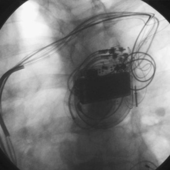
Radiographic examination of leads serves two purposes.142 First, it allows the physician to ascertain the presence of unipolar versus bipolar distal electrodes and the fixation mechanism. Distal active-fixation screws may often be seen directly on radiography, whereas passive-fixation leads have a bulbous tip. Second, radiographic examination may identify lead conductor fractures in which the conductor has clearly separated, leaving a gap, especially with magnified views (Fig. 24-10). Lead information of this sort is important for programming, for selecting an appropriately compatible generator, and for identifying leads for extraction. Fluoroscopy also gives some indication of the degree of fibrosis evident through the real-time motion of the lead and surrounding calcification, information that could be useful if extraction is required.
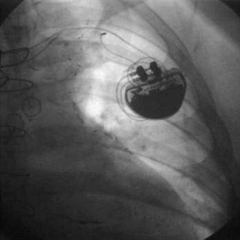
Radiography of leads involves an examination of the insertion site (e.g., subclavian, axillary, cephalic, jugular, or epicardial), acute bends or fractures in the lead, the location of lead coils beneath the pulse generator (in the event they need to be freed for lead repositioning or extraction), the position of the pulse generator connector block, and a general preview of the character of the connector block–lead interface (Fig. 24-11; see also Fig. 24-9). The lead should be examined fluoroscopically throughout its course for kinking, fracture, or excessive tension as well as for fixation at the distal tip. A thorough radiographic examination of lead integrity and pulse generator–lead interface before reoperation in pacemaker and ICD patients can save much distress when the pocket is opened.
Invasive Evaluation
Measuring Functional Capacity of Implanted Leads
One of the most crucial parts of invasive analysis during reoperation involves measurement of pacing and sensing capabilities in existing leads. Vigorous noninvasive evaluation should provide the operator with valuable information on lead viability and functional status,51,58,64,79,91 although verification of lead integrity and precise DFT determination must be performed at the surgical procedure. If surgery is undertaken for pulse generator replacement, demonstrating viability of existing leads is vital to the appropriate long-term performance of the new battery. Surgery for lead repair or revision itself involves extensive testing of chronic leads to confirm the lead as the source of malfunction, ensure normal operation of other leads, and evaluate new leads for optimal positioning inside the heart.
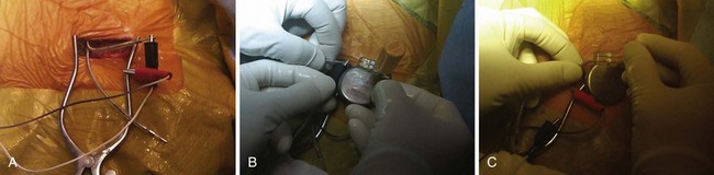
After the pacemaker or ICD pocket is opened, the pulse generator is disconnected from the leads to enable testing of lead sensing and pacing functional capacity.143 The lead must be disconnected from the pulse generator cautiously in pacemaker-dependent patients. To avoid prolonged ventricular asystole, the operator must be prepared to connect the lead immediately to a cable attached to a functioning external pacing system (Fig. 24-12). The external device should be activated and should be delivering pacing impulses before the ventricular lead is disconnected from the pulse generator in a pacemaker-dependent patient. Alternatively, although usually unnecessary, a temporary pacing wire may be placed before disconnecting a lead in a pacemaker-dependent patient; however, such additional instrumentation may increase the risk of infection. As always, the operator must exercise care not to cut the lead.
Testing the Sensing and Pacing Capabilities of Long-Term Leads
Another crucial aspect of invasive testing involves measurement of pacing and sensing thresholds in long-term implanted pacemaker and ICD leads. Most leads show some deterioration in pacing and sensing thresholds during the first 4 to 8 weeks after implantation, then reach a relatively stable level for the long term.46,88 However, thresholds may continue to increase over time, a change that may now be recognized by remote monitoring. The change in threshold from baseline was greatest with active-fixation, non-steroid-eluting leads; threshold increases are reduced with passive fixation and steroid elution on all lead types. Noninvasive testing should alert the operator to the usefulness of long-term leads, but invasive testing and inspection confirm their functional utility.
Inadequate sensing or pacing thresholds at generator replacement are indications for placement of a new lead in the affected chamber. This may entail either capping an old lead and leaving it in place or removing it. The new lead can usually be placed through the same subclavian or axillary vein; although it is preferable to avoid having too many leads, especially more than four, pass through the same vessel, to reduce the chance of venous occlusion and thrombosis.144 A single new lead may also be placed through the internal jugular vein, external jugular vein, the contralateral subclavian or axillary vein, or deep into the innominate vein.145 The proximal tip can be tunneled to the original pocket to meet a second, functional long-term lead for a dual-chamber pacemaker system if required. Alternatively, an entirely new generator or lead system may be placed on the contralateral side.146 Lead extraction allows placement of new leads through a conduit produced by lead removal.
Examining Structural Integrity of Leads and Lead-Generator Interface
Visual inspection at surgery provides clues to lead integrity. Fluid inside the lead body suggests an outer insulation break but, especially in coradial pacing leads, does not necessarily mandate lead replacement. Fluid can be identified routinely in CS leads with an open lumen. Undue tension on the lead near the fixation site may cause kinking, conductor uncoiling, conductor fracture, or thinning of the electric insulator. A hazy appearance of the insulator surrounding an area of tension or repeated stress is common in earlier leads. This appearance represents surface erosion of the lead insulator and does not itself imply lead malfunction. However, the finding should alert the operator to potential lead damage in areas of stress to the insulation. An examination of the suture location ensures that the ligature remains around the suture sleeve, and gentle tension on the lead body ensures its fixation at the venous entry site. Visual inspection of the specific course of a coiled lead in the pocket may be hampered by a significant thickness of overlying capsule scar; fluoroscopy can assist in this regard.75–78 Be ready for any surprise, such as a “twiddled” lead (Fig. 24-13).
Direct examination of the lead connector can assist in the identification of the lead model if not previously known.100–102 This is particularly important for lead models that have excessive premature failure rates; such leads in the ventricular position should routinely be replaced in pacemaker-dependent patients.
Venography
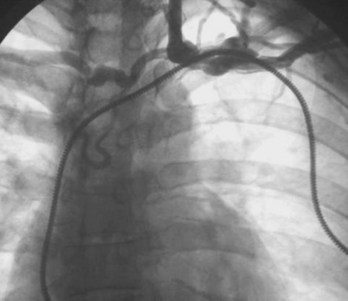
Venography is indicated when the subclavian, axillary, or cephalic veins cannot be accessed (to demonstrate their locations), when the veins are accessed but a guidewire cannot be passed into the SVC, and when lead upgrade is required in the presence of long-standing prior lead implant durations. Inability to access the subclavian vein that carries a previously implanted lead suggests either an incorrect needle insertion angle or an occluded subclavian or brachiocephalic venous system.127–131,147–151 Finding an appropriate location to insert the access needle can be facilitated by advancing the needle fluoroscopically in the direction of the chronic electrode under the clavicle, with care not to damage the implanted lead. The vein should be approached with the bevel of the needle facing the implanted lead. If access is not possible, venography may provide better delineation of the course of the axillary or subclavian vein. In this situation, radiopaque dye must be injected distal to the veins to be visualized, that is, into the basilic or median cubital vein.
Occasionally, access to the axillary or subclavian vein is possible, but the guidewire will not pass freely to the SVC. If needle placement in the vessel is adequate, failure to pass a wire suggests proximal venous occlusion.128,147,152–156 Venography demonstrates whether occlusion is indeed present and, if so, its site. Chronic venous occlusion may occur asymptomatically in conjunction with the development of collateral venous circulation around the shoulder. Delineation of the location and length of occlusion indicates to the operator an appropriate needle insertion site for placement of a new lead. It also ensures patency of the SVC. Dye is injected directly into the subclavian vein through the insertion needle; this local venogram gives the best opacification. Occlusion of the brachiocephalic system proximal to the junction of the internal jugular vein excludes the ipsilateral jugular system as an alternative site for a new lead. Alternatively, if the subclavian vein is occluded and the internal jugular vein remains patent, a new lead may still be placed using the jugular approach. Occlusion of the SVC precludes the use of any new endocardial lead placed from a superior site unless leads are extracted to produce a conduit.157 Although venoplasty is acceptable, stents should never be placed into veins without removal of preexisting leads, so as to avoid trapping the leads between a stent and the vein wall (Fig. 24-14).
A persistent SVC (which usually drains into the coronary sinus) makes placement of RV endocardial leads difficult or impossible.158,159 In some cases of venous occlusion, it may facilitate placement of a lead system.130 Venography defines the anatomy of the venous system in such a situation, which may be suggested by an unusual intravascular guidewire course. Finally, leakage of venography dye into perivascular tissues or into the pericardial space suggests vessel or cardiac chamber perforation, respectively.
 Surgical Considerations
Device replacement or revision in a tertiary care institution, with an active electrophysiology service following the patient for the long term, accounts for 30% to 40% of all pacemaker and ICD procedures. The timing of intervention depends on the specific indication. Most patients require reoperation for elective battery replacement or battery or lead revision, whereas 1% to 6% of patients return to the laboratory for other problems, such as pocket hematoma, pocket twitch, diaphragmatic pacing, and pocket relocation (see Box 24-1).
Elective Device Replacement or Revision
Most reimplantation procedures are either elective or performed for repair or replacement of prior devices. Preoperative blood analysis is performed. Aspirin and clopidogrel are not stopped before the procedure unless a compelling medical reason exists; stopping these medications can lead to myocardial infarction. Warfarin may be discontinued for 3 to 5 days for procedures in which the major vessels will be instrumented, although more frequently, patients receiving warfarin undergo implantation and revision, because the risk of hematoma development is much higher with heparin and enoxaparin than with warfarin.140
The patient fasts from midnight and receives preoperative antibiotics, usually being admitted on the day of the procedure. Elevated coagulation times may be corrected with fresh-frozen plasma if necessary. Procedures are routinely performed with local or regional anesthesia, supplemented by intravenous (IV) conscious sedation. For ICDs, the patient is given general anesthesia for ventricular fibrillation induction and DFT testing. Most institutions use a combination of a short-acting, amnestic benzodiazepine such as midazolam together with an IV narcotic for analgesia. Continuous electrocardiographic monitoring, pulse oximetry, and sterile preparation and draping are standard procedures. Preoperative antibiotics are administered intravenously. Midazolam provides excellent amnesia for the procedure.160
General Guidelines and Techniques
There is no substitute for careful surgical planning in approaching the established pacemaker pocket and gentle handling of the tissues. Perfect hemostasis, avoidance of a tight-fitting pacemaker or ICD pocket, and multilayered incision closure are the basic principles that help prevent future difficulties. These principles are similar to those required at initial implantation (see Box 24-2). To avoid induction of ventricular fibrillation, development of fibrosis at the lead tip, and damage to the generator itself, electrocautery must not be used directly over an implanted pulse generator with unipolar leads. This issue has become much less of a problem with the current exclusive implantation of bipolar leads. Electrocautery can be used safely during battery changes as long as the leads are not grounded to the patient, to avoid current shunting directly to the heart. Hemostasis at reoperation can usually be secured with electrocautery or direct ligature. Use of surgical absorbable cellulose or topical thrombin assists in treating persistently oozy pockets. Clinical judgment should be used in the application of various technical approaches (Fig. 24-15).
Specific Techniques
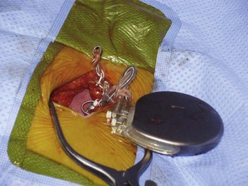
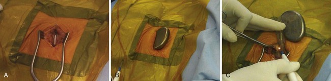
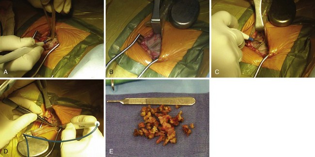
The surgical incision is placed directly over the previous incision. The skin and subcutaneous tissues are opened with sharp dissection, which is required to penetrate the tough scar tissue and dermal layer. Deeper dissection with Metzenbaum scissors or electrocautery is carried out to delineate the pacemaker capsule. Once the pocket is reached, the fibrous capsule is sharply incised and then extended under direct visualization of the implanted pulse generator and leads. The capsule must be opened far enough to allow extraction of the pulse generator and lead connector assembly without undue force. The posterior capsule should be carefully dissected away from the leads to allow mobility. Access to leads and generator may be facilitated through the use of self-retaining retractors. Extreme care is required throughout the procedure to preserve the integrity of the leads and lead connectors; they must not be punctured with anesthetic needles or cut with blades or scissors. If electrocautery is used to remove tissue from the leads in dissecting them from scar tissue in the posterior capsule, the probe must keep moving over the lead so as to not overheat the lead insulation and thereby damage it. Leads with very thin insulation, including coradial leads and most coronary sinus electrodes used with BiV systems, are more prone to heat damage from electrocautery because of their thin outer insulators (Fig. 24-16).
Once the generator is delivered out of the pocket, the leads are disconnected and analyzed. Leads from pacemaker-dependent patients need to be expeditiously reconnected to an external pacemaker (see Fig. 24-12). Unipolar pacemaker leads require direct grounding to subcutaneous tissue; the active part of the unipolar generator must remain in contact with the patient before the lead is disconnected. Grounding can best be accomplished through a large-surface-area ground electrode placed directly into the open pocket. Making contact with this electrode onto the active surface of a unipolar pulse generator allows the generator to be removed safely from the pocket before the lead is disconnected, even in a pacemaker-dependent patient.
After being secured to temporary pacing cables, leads can be completely freed of adhesions up to their entry point into the subclavian vein, if necessary, to examine lead integrity or for extraction. We use low-energy electrocautery sparingly to dissect the leads free of adhesions, because the scar tissue could be especially tough and adherent to lead structures. If lead replacement or repair is not necessary, and if the function of previously implanted leads is adequate, dissection of the complete course of each lead may not be necessary, as long as lead connector mobility is sufficient to attach it to a new pulse generator without tension (Fig. 24-17).
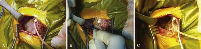
At generator replacement or revision, the old capsule should be incised or removed. We open the capsule in a medial and inferior direction because (1) a new device, even if an identical model to the one removed, will never fit perfectly in the original pocket without tension, and (2) doing so allows for absorption of fluid and fresh blood flow, which are not possible if the relatively avascular capsule is left intact. This reduces the risk of infection, which is higher at generator replacement than at initial device implantation161 (Fig. 24-18).
In very thin patients, subpectoral or axillary locations may be required. The physician can access the subpectoral plane by locating the junction between the sternal and clavicular heads of the pectoralis major muscle and making entry at that point, taking care to avoid damage to penetrating neurovascular bundles. As a secondary approach, the deltopectoral groove can be similarly approached. Alternatively, the muscle fibers of the pectoralis major can be teased apart longitudinally to allow entry to the subpectoral plane. Axillary subcutaneous placement of a pacing device is generally avoided because of the possibility of lateral migration of the device, which can be uncomfortable for the patient and, especially with larger ICDs, can lead to erosion. When required, however, the axillary location can be entered through direct extension from a subclavian pocket or through a separate axillary incision.162 The device may be secured in placed in a subpectoral location at that site for more stability (Fig. 24-19). The abdominal wall, subcostal, intrathoracic, and transiliac positions represent other alternatives for a replacement pulse generator.163 Nevertheless, a subcutaneous prepectoral approach is appropriate in most patients for both pacemaker and ICD reimplantation.
Upgrade to Biventricular System
Venous Access
Current lead extraction guidelines recommend that no more than four leads pass through either subclavian vein, and that no more than five leads pass through the SVC.144 Lead extraction is indicated to prevent vascular overload and occlusion. After extraction, with fewer leads in place, standard axillary or brachiocephalic access techniques can be used to place an additional CS lead. In the event of upgrade from a pacemaker to a BiV ICD, an additional high-energy lead is also needed, so extraction of the preexisting ventricular pacemaker electrode may be indicated. The simple addition of a CS lead in a patient with a patent ipsilateral vessel is straightforward. Rarely are the other leads affected or dislodged; placing straight stylets down each of the existing leads while the CS lead is added gives the preexisting leads additional security, especially if relatively new.
Special Precautions
All the additional manipulation required to place a CS lead or upgrade any system to a BiV device adds time and complexity to the revision procedure. This poses an additional infective risk to a procedure (generator replacement) that already carries an increased risk of infection compared to an initial device implantation. Thus, a meticulously sterile approach is mandatory, despite all the additional time and tools required.161
 Generator Lead Adaptability
Lead Connectors
Replacing a pulse generator onto one or more chronic leads requires that the pulse generator connector block be compatible with the proximal lead tip.100–102 Through years of development by multiple manufacturers, pacemaker leads have evolved to an International Standard (IS-1) proximal lead connector configuration, which consists of (1) a 3.2-mm lead connector with a short pin that is electrically connected to the distal electrode tip, (2) a lead connector ring wired to the proximal pacing pole, and (3) sealing rings. The proximal lead connector configuration is the same for unipolar and bipolar leads, except that the ring is inactive in unipolar leads. Modern pulse generators have connector block specifications that conform to IS-1 leads; some also fit the prior Voluntary Standard (VS-1) lead type. Thus, generator replacement onto implanted leads of either of these two types poses no difficulty because of the wide array of compatible pulse generators from multiple manufacturers.
Before the availability of IS-1 and VS-1 lead connector configurations,100,101 the most common pacemaker leads were 3.2-mm low-profile leads (unipolar or linear bipolar), 5-mm or 6-mm unipolar and linear bipolar leads, and bifurcated bipolar systems. Pacemaker pulse generators available from some manufacturers remain compatible with each of these lead models, especially 3.2-mm and 5- or 6-mm linear bipolar and unipolar leads. Precise compatibility, however, is essential to ensure that no fluid leaks into the pulse generator connector block and that electrical continuity to proximal and distal poles remains intact. The implanting physician must be particularly cautious to ensure that sealing rings are located either on the lead connector or in the pulse generator connector block, because not all early lead models had sealing rings placed on the lead connector itself.
Similarly, ICD leads have evolved to incorporate IS-1 pace/sense connectors with concomitant IS-1 atrial and ventricular ports in the generator connector block to attach these leads. Early-generation ICDs, however, used a wide variety of lead port sizes and configurations, requiring the operator to have available generators with various header port sizes, adapters, and upsizing sleeves for reoperation of early ICD generators implanted before the adoption of a uniform standard. Even CS lead ports have evolved from an LV-1 configuration without sealing rings to the IS-1 configuration (Fig. 24-20).
Because a variety of other lead connector configurations had previously been developed, and because early models of implanted leads may remain useful for many years and still exist, although in a gradually decreasing percentage of patients, a number of these older lead connector configurations remain in use (Table 24-1). If sensing and pacing thresholds are adequate, early leads with such configurations may be used, but a pacemaker or ICD pulse generator with a compatible connector block needs to be selected. As with pacemakers, ICD generator connector blocks from some manufacturers are available in a variety of configurations and port sizes to attach directly to existing implanted leads (Fig. 24-21). An alternative (but less desirable) approach involves using an adapter to fit odd-sized lead connectors into available ports on the ICD header block.
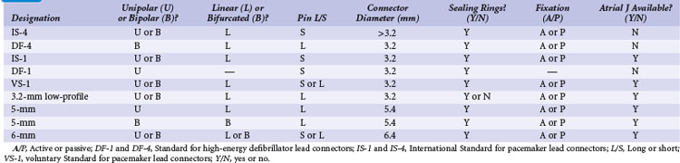
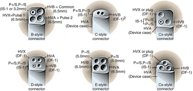
Figure 24-21 Implantable cardioverter-defibrillator header connector block configurations.
(From ICD replacement guide. Medtronic, Minneapolis.)
Defibrillator (high voltage) and pacemaker (low voltage) standards have continued to progress with the development of a quadripolar 3.2-mm standard. This has been introduced as DF-4 for combined pacing and shocking applications and is under development as IS-4 for dedicated low-voltage applications (see Fig. 24-8). The terminal pin and first ring carry low-voltage impulses in both applications and for all four poles in the low-voltage application. The most anticipated application, DF-4, replaces the trifurcated ICD lead combining the function of one IS-1 and up to two DF-1 connectors (Fig. 24-22). The new DF-4 lead header simplifies connection to the pulse generator. At reoperation, it eliminates the need to dissect out the trifurcation of the high-energy lead for mobility in the pocket. However, the introduction of this connector creates new problems, with the need for new adapters in the event that a separate rate-sensing lead or an additional high-energy lead is required. Extra care is appropriate during intraoperative evaluation to connect testing cables correctly.111
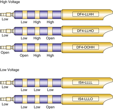
Figure 24-22 Configurations for DF-4 and IS-4 leads.
(From Proposed IS-4 Standard; American Association of Medical Instrumentation presentation at Cardiostim, Nice, France, 2004; and ISO Standard: Active implantable medical devices: four-pole connector system for implantable cardiac rhythm management devices—dimensional and test requirements. Geneva, 2009, International Standards Organization—E:\ISO FDIS 27186 (E) 25June2009.doc STD Version 2.1c2.)
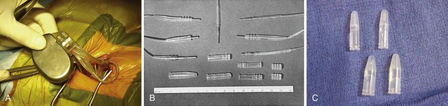
Adapters
The two general categories of adapters available are (1) electrically conducting units that change the size or configuration of lead connectors to fit specific pulse generators and (2) upsizing sleeves that allow IS-1 or 3.2-mm, low-profile leads to fit into 5- or 6-mm pulse generator connector blocks while maintaining a fluid seal, or a similar sleeve to upsize an LV-1 header to an IS-1 header for a CS lead (Table 24-2 and Fig. 24-23).
TABLE 24-2 Common Configurations for Pacemaker or Defibrillator Adapters
| From (Lead) | To (Generator) |
|---|---|
| Conducting Adapters | |
| 6-mm UNI | 5-mm UNI |
| 6-mm BIF | 3.2-mm LP BI |
| 6-mm BI | 3.2-mm LP BI |
| 5-mm BIF | 3.2-mm LP BI |
| 5-mm BIF | IS-1 BI |
| 5-mm UNI | IS-1 UNI |
| 3.2-mm LP BI | 5-mm BIF |
| 3.2-mm LP | IS-1 BI |
| DF-1 + DF-1 | DF-1* |
| Nonconducting Upsizing Sleeve Adapters | |
| 3.2-mm LP BI | 5-mm or 6-mm UNI (+ pin extender) |
| IS-1 UNI or BI | 5-mm or 6-mm UNI |
| 5-mm UNI | 6-mm UNI |
| LV-1 | IS-1 |
BI, Linear bipolar; BIF, bifurcated bipolar; LP, low profile; UNI, unipolar.
* Used for the addition of a subcutaneous lead, patch, or array to an endocardial high-energy lead.
Electrically conducting adapters necessarily contain wires attached on one end to a lead pin to enter the new pulse generator and a socket on the other to accept the old lead as well as a mechanism to connect the old lead, generally a set screw. Produced by most manufacturers, adapters are available in an array of types (see Table 24-2). The most common pacemaker adapters downsize 5- or 6-mm leads to IS-1 unipolar or bipolar configurations or adapt 3.2-mm low-profile connectors to the IS-1 variety. Adapters are also available to convert bifurcated bipolar leads to the linear IS-1 bipolar configuration.
Adapters for ICD leads may be used either for the rate-sensing (pace/sense) leads or for the high-energy leads, patches, or arrays (Fig. 24-24). These small units are most helpful for adapting epicardial lead connectors found in an abdominal pocket to newer-generation ICD batteries, that is, attaching nonstandard lead connectors to IS-1 pacing and DF-1 shocking ports in an ICD header block. The adapters may also be used when older transvenous leads must be attached to newer, standard-connect ICD pulse generators.
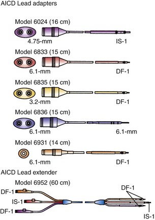
Figure 24-24 Implantable cardioverter-defibrillator lead adapters.
(From Multiple options for customized therapy. Guidant, St Paul, Minn.)
Despite the available variety of electrically conducting adapters, these units prove bulky in the pacemaker or ICD pocket (Fig. 24-25) Furthermore, they provide another electrical weak link, that is, one additional set of connections in the pacing circuit for delivery of current to the patient and for sensing, increasing the chance of malfunction, compared with direct attachment of a lead into a pulse generator connector block. Some adapter set screws must be sealed with medical adhesive after being fastened to the lead; a poor seal can result in a short circuit in the system. Because of internal connections, not all adapters have the reliability inherent in most pacemaker or ICD leads directly connected to the generator.
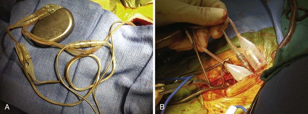
Figure 24-25 Pocket bulk from adapters.
A, Bulk in pocket with transvenous lead. Lead header connections from the same patient as in Figure 24-20, A. It is clear that adding adapters increases pocket bulk. In the center of the figure is a linear adapter that takes a long, IS-1 pace/sense electrode to adapt it to a bifurcated, bipolar, 5-mm side-by-side lead, to allow its connection to the pulse generator. The side-by-side pace/sense portion of the original trifurcating, high-energy lead has two 5-mm caps in place, likely because of pace/sense malfunction at the previous generator change. Two 6-mm high-energy lead heads attach from the high-energy lead directly into the pulse generator. Options for replacement here include obtaining a pulse generator that adapts directly to these leads, which is the best option. Alternatively, the pace/sense adapter could be removed (not always possible) and the high-energy lead heads adapted to DF-1. If upgrade is required, new adapters to DF-1 would be necessary. B, Adapter mass in pocket. Multiple lead adapters deigned to maintain use of existing leads and connect them to a new pulse generator. The degree of bulk in the pocket is extreme, which can lead to discomfort and an increased risk of erosion.
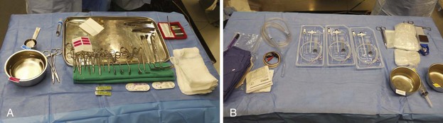
Tools
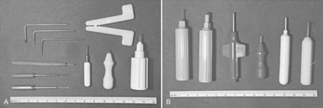
Several specially designed tools assist the operator in replacing pacemaker and ICD pulse generators and repairing leads (Box 24-6 and Fig. 24-26). Most important are wrenches to loosen set screws in the pulse generator connector block to allow the old lead to be withdrawn. Set-screw sizes are now standardized, but if the original generator manufacturer and model are known, a specific wrench may be required. Some early pulse generators had to be removed from the lead with a small, flat screwdriver. Some pulse generators were connected to the lead without set screws through pressing of an attachment unit into place; loosening this unit required that a small probe be inserted into the side of the connector block to push open the locking mechanism. It is unusual to lose set screws because they are generally held in place by a seal. It is advisable, however, to have additional set screws available in a busy pacing laboratory.
Approach to the Eroding Device
Although relatively uncommon, chronic erosion through the skin by the pulse generator or lead can occur.1,13,135 Incipient erosion manifests as localized erythema in an area of thinned skin that is adherent to the underlying device. The area gradually becomes necrotic and may drain serosanguineous fluid. Outright erosion and drainage necessarily imply that the pacemaker pocket is no longer sterile;1,164 the system (generator and leads) should be removed in such cases.5,8,9 Occasionally, the pocket heals with removal of the pulse generator alone, but only when skin integrity has not been breached. However, even a near-erosion is more often a manifestation of a chronic indolent infection and rarely is adequately treated without removal of the leads as well as the device (see Chapter 26). After removal of the pulse generator and leads, eroded pockets can be fully debrided and closed primarily, leaving a drain in place for 2 to 3 days; pockets rarely need to be packed for closure by secondary intention. IV antibiotics are administered for 1 week up to 6 weeks, if bacteremia is present.
A new device should be implanted on the contralateral side only after all signs of infection have resolved at the original pacemaker site, and if the patient has not experienced recurrent fever, the white blood cell count has not increased, and no tricuspid valve vegetation is seen. Two to five days of IV antibiotics appears sufficient before device replacement, as long as bacteremia has resolved and there are no large, intracardiac vegetations. Replacement of the pulse generator on the original side is not recommended; however, this may be possible if complete erosion did not occur, if the pocket could be closed after primary removal of the generator, and if there are no signs of active infection after discontinuation of antibiotics. Alternative approaches are discussed in Chapter 21.
Antibiotic Prophylaxis
The use of broad-spectrum antibiotics for antimicrobial prophylaxis during all procedures involving generator or lead revision is essential. This is especially crucial because these procedures use combinations of previously implanted hardware with new equipment, and because the incidence of infection is increased with generator change or pocket revision. Controversy surrounds whether and how long to use postoperative antibiotic prophylaxis.10,164
 Intervention for Acute Problems
Indications for acute intervention include primary complications of pacemaker or ICD implantation (e.g., pocket hematoma, infection,1–3 or cardiac perforation126–135) as well as other, less crucial indications, such as iatrogenic lead damage and lead dislodgment.
Pocket hematomas occur most often in patients receiving anticoagulants, especially heparin and enoxaparin, and in patients with platelet dysfunction, which is common in those undergoing long-term hemodialysis. The range in hematoma size varies from a contained, small amount of fluctuance and ecchymosis to a large hematoma that may drain through the skin. A minor hematoma requires only observation, whereas a breach of skin integrity after operation may require evacuation of the hematoma or, if it has become secondarily infected, complete removal of the generator and lead system. If the patient remains pacemaker dependent, a temporary wire must be placed when the original system is removed; after an appropriate course of IV antibiotic therapy, a new device can be placed on the contralateral side. Prolonged antibiotic therapy may be required in some cases. Antibiotic therapy alone and conservative surgical approaches other than complete removal of an eroded or infected generator and leads prove unsatisfactory.5–810
Immediate reoperation may also be required for cardiac perforation.132–137 Perforation is suggested by curvature of the lead beyond the confines of the right ventricular apex, an abrupt rise in pacing threshold or deterioration of sensing, precordial pain that increases with inspiration, hypotension, and hemodynamic collapse. Although most perforations close spontaneously, development of a large, pericardial bleed or tamponade requires immediate intervention.137 Pericardiocentesis usually suffices, but occasionally, a subxiphoid approach to pericardial drainage is necessary. Proper lead selection to match the patient’s anatomy and gentle technique are vital to avoiding acute perforation. Subcostal placement of epicardial screw-in leads has been associated with a higher-than-expected incidence of serious or fatal ventricular perforations; chronic perforation by endocardial leads is distinctly rare.
Early surgical exploration is indicated to confirm the diagnosis of iatrogenic lead insulation damage. This is an uncommon complication that manifests early in the form of “pocket twitch,”141 failure to capture, or failure to sense, often with associated low measured lead impedance.91 Chronic lead damage has been associated with excessively tight anchoring sutures, especially if they are placed around the lead and not the anchoring sleeve. The damaged lead, whether passive or active fixation, should be removed and replaced, if possible; alternatively, it may be repaired, although repair is difficult if damage has occurred near the venous insertion site.
Lead dislodgment occurs most frequently during the first 24 to 48 hours after system implantation.49,50 It can occur later, however, as a result of a loose anchoring sleeve, incomplete fixation of the distal lead tip, excessive diaphragmatic motion, or patient manipulation of the device (i.e., twiddler’s syndrome).87 Before the development of leads with active fixation or a finlike mechanism at the distal tip, the incidence of lead dislodgment ranged as high as 5% to 18%. With careful technique and selection among a variety of active-fixation and passive-fixation leads, the incidence should range no higher than 1% to 2%.59,60 Most spontaneous dislodgments occur with atrial passive-fixation leads. The diagnosis may be facilitated by chest radiography or fluoroscopy; pacing analysis reveals an increased pacing threshold, usually with normal lead impedance. The operator has the option of repositioning or replacing the lead. If a distinct cause cannot be identified, placement of an active-fixation lead may avoid a second dislodgment. To prevent recurrent lead dislodgment in twiddler’s syndrome, leads must be sutured to prepectoral fascia or firm, fibrous, pacemaker pocket tissue with nonabsorbable sutures around anchoring sleeves at more than two points; the pacemaker connector block may also need to be anchored to the pectoralis fascia. A polyester (Dacron) pouch has been used in the past to improve device stability in twiddler’s syndrome and in patients with very loose subcutaneous tissue,165 but it is rarely required at present. Removal of the pouch may be difficult at generator replacement (Fig. 24-27). Newer, antibiotic-impregnated, nonabsorbable pouches may be even more difficult to remove166,167 (Fig. 24-28).
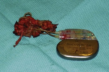
Figure 24-28 Explanted antibiotic-impregnated pouch.
Although the degree of fibrosis is significant, this pouch (Tyrx, Monmouth Junction, NJ), unlike the Dacron pouch from Figure 24-27, has a glistening internal surface because it is less predisposed to embed itself around the lead coils in the pocket. Nevertheless, removal of the pouch is difficult because of extensive scarring to the capsule inside the device pocket.
Interval or Unscheduled Intervention
In the course of pacemaker or ICD follow-up and before the patient requires elective replacement, interval intervention may be needed to correct other complications. These include pulse generator migration,30 lead dislodgment,* high pacing thresholds,46,88 pocket twitch or diaphragmatic pacing,141 lead insulation break or lead fracture,17,19,22,23 premature generator failure (which could be caused by intrinsic component failure or externally induced failure, as caused by electrocautery, irradiation, or cardioversion),29 and the need for system upgrade.35–43126 The device clinic or remote monitoring may prove particularly useful in recognizing early surgical or functional problems.63–73 Evaluation and technique follow the principles described earlier.
 Conclusion
Successful pacemaker or ICD replacement is the result of accurate preoperative evaluation and careful surgical intervention. Complication rates of pulse generator replacement and lead revision exceed those of initial implantation.161 The preoperative status of the pulse generator battery and the lead pace/sense function, as well as the appropriateness of both to future pacing or defibrillating systems, needs to be determined to enable surgical planning. There should be no surgical surprises, and all the tools, adapters, leads, and generators should be ready for the intervention. The goal should be to avoid reoperation for as long as possible with careful initial implantation and programming. When properly planned, surgery is likely to proceed smoothly.
1 Bonchek LI. New methods in the management of extruded and infected cardiac pacemakers. Ann Surg. 1972;176:686.
2 Corman LC, Levison ME. Sustained bacteremia and transvenous cardiac pacemakers. JAMA. 1975;233:264.
3 Wohl B, Peters RW, Carliner N, et al. Late unheralded pacemaker pocket infection due to Staphylococcus epidermidis: a new clinical entity. Pacing Clin Electrophysiol. 1982;5:190.
4 Prager PI, Kay RH, Somberg E, et al. Pacemaker remnants-another source of infections. Pacing Clin Electrophysiol. 1984;7:763.
5 Ruiter JH, Degener JE, Van Mechelen R, Bos R. Late purulent pacemaker pocket infection caused by Staphylococcus epidermidis: serious complications of in situ management. Pacing Clin Electrophysiol. 1985;8:903.
6 Vilacosta I, Zamorano J, Camino A, et al. Infected transvenous permanent pacemakers: role of transesophageal echocardiography. Am Heart J. 1993;125:904.
7 Ruttmann E, Hangler HB, Kilo J, et al. Transvenous pacemaker lead removal is safe and effective even in large vegetations: an analysis of 53 cases of pacemaker lead endocarditis. Pacing Clin Electrophysiol. 2006;29:231-236.
8 Sohail MR, Uslan DZ, Khan AH, et al. Management and outcome of permanent pacemaker and implantable cardioverter-defibrillator infections. J Am Coll Cardiol. 2007;49:1851-1859.
9 Klug D, Balde M, Pavin D, et al. Risk factors related to infections of implanted pacemakers and cardioverter-defibrillators: results of a large prospective study. PEOPLE Study Group. Circulation. 2007;116:1349-1355.
10 Baddour LM, Epstein AE, Erickson CC, et al. American Heart Association Rheumatic Fever, Endocarditis, and Kawasaki Disease Committee; Council on Cardiovascular Disease in Young; Council on Cardiovascular Surgery and Anesthesia; Council on Cardiovascular Nursing; Council on Clinical Cardiology; Interdisciplinary Council on Quality of Care; American Heart Association: Update on cardiovascular implantable electronic device infections and their management: a scientific statement from the American Heart Association. Circulation. 2010;121:458-477.
11 Grammes JA, Schulze CM, Al-Bataineh M, et al. Percutaneous pacemaker and implantable cardioverter-defibrillator lead extraction in 100 patients with intracardiac vegetations defined by transesophageal echocardiogram. J Am Coll Cardiol. 2010;55:886-894.
12 Voigt A, Shalaby A, Saba S. Continued rise in rates of cardiovascular implantable electronic device infections in the United States: temporal trends and causative insights. Pacing Clin Electrophysiol. 2010;33:414-419.
13 Garcia-Rinaldi R, Revuelta JM, Bonnington L, Soltero-Harrington L. The exposed cardiac pacemaker: treatment by subfacial pocket relocation. J Thorac Cardiovasc Surg. 1985;89:136.
14 Gold MR, Peters RW, Johnson JW, Shorofsky SR. Complications associated with pectoral cardioverter-defibrillator implantation: comparison of subcutaneous and submuscular approaches. Worldwide Jewel Investigators. J Am Coll Cardiol. 1996;28:1278-1282.
15 Tsai V, Chen H, Hsia H, et al. Cardiac device infections complicated by erosion. J Interv Card Electrophysiol. 2007;19:133-137.
16 Hamid S, Arujuna A, Ginks M, et al. Pacemaker and defibrillator lead extraction: predictors of mortality during follow-up. Pacing Clin Electrophysiol. 2010;33:209-216.
17 Kronzon I, Mehta SS. Broken pacemaker wire in multiple trauma: a case report. J Trauma. 1974;14:82.
18 Tegtmeyer CJ, Bezirdjian DR, Irani FA, Landis JD. Cardiac pacemaker failure: a complication of trauma. South Med J. 1981;74:378.
19 Grieco JG, Scanlon PJ, Pifarre R. Pacing lead fracture after a deceleration injury. Ann Thorac Surg. 1989;47:453.
20 Catanzaro JN, Makaryus AN, Jadonath S, Jadonath R. Pacemaker ventricular lead microdislodgement following a motor vehicle accident. Eur J Emerg Med. 2007;14:224-227.
21 Hai AA, Kalinchak DM, Schoenfeld MH. Increased defibrillator charge time following direct trauma to an ICD generator: blunt consequences. Pacing Clin Electrophysiol. 2009;32:1587-1590.
22 Chen WL, Chen YJ, Tsao YT. Traumatic pacemaker lead fracture. J Trauma. 2010;69:E34.
23 Fernández-González AL, García Bengochea JB, Cortés Laíño J, et al. Fracture of epicardial resynchronization lead caused by deceleration injury. Asian Cardiovasc Thorac Ann. 2010;18:77-78.
24 Wallace WA, Abelmann WH, Norman JC. Runaway demand pacemaker: report, in vitro reproduction, and review. Ann Thorac Surg. 1970;9:209.
25 Austin SM, Kim CS, Solis A. Electrical alternans of pacemaker spike amplitude: an unusual manifestation of permanent pacemaker generator malfunction. Pacing Clin Electrophysiol. 1981;4:313.
26 Campo A, Nowak R, Magilligan D, Tomlanovich M. Runaway pacemaker. Ann Emerg Med. 1983;12:32.
27 Lewinn AA, Serago CF, Schwade JG, et al. Radiation-induced failures of complementary metal oxide semiconductor containing pacemakers: a potentially lethal complication. Int J Radiol Oncol Biol Phys. 1984;19:1967.
28 Venselaar JL, Van Kerkeorle HL, Vet AJ. Radiation damage to pacemakers from radiotherapy. Pacing Clin Electrophysiol. 1987;19:538.
29 Maisel WH. Pacemaker and ICD generator reliability: meta-analysis of device registries. JAMA. 2006;295:1929-1934.
30 Bello A, Yepez CG, Barcelo JE. Retroperitoneal migration of a pacemaker generator: an unusual complication. J Cardiovasc Surg. 1974;15:256.
31 Kim GE, Haveson S, Imparato AM. Late displacement of cardiac pacemaker electrode due to heavyweight pulse generator. JAMA. 1974;228:74.
32 Lorsheyd A, De Boeck BW, Guyomi SH, Klöpping C. A wandering defibrillator lead. Eur J Echocardiogr. 2009;10:156-159.
33 Tay JK, Dweck MR, Francis CM, Grubb NR. Unusual complication of a migrant pacemaker lead. Europace. 2009;11:1122-1124.
34 Hörer T, Vidlund M, Lindell P, Jansson K. A rare case of pacemaker electrode perforation of the heart with intra-abdominal migration. Clin Cardiol. 2010;33:E20.
35 Korley VJ, Hallet N, Daoust M, Epstein LM. A novel indication for transvenous lead extraction: upgrading implantable cardioverter defibrillator systems. J Interv Card Electrophysiol. 2000;4:523-528.
36 Baker CM, Christopher TJ, Smith PF, Langberg JJ, et al. Addition of a left ventricular lead to conventional pacing systems in patients with congestive heart failure: feasibility, safety, and early results in 60 consecutive patients. Pacing Clin Electrophysiol. 2002;25:1166-1171.
37 Höijer CJ, Meurling C, Brandt J. Upgrade to biventricular pacing in patients with conventional pacemakers and heart failure: a double-blind, randomized crossover study. Europace. 2006;8:51-55.
38 Leclercq C, Cazeau S, Lellouche D, et al. Upgrading from single chamber right ventricular to biventricular pacing in permanently paced patients with worsening heart failure: the RD-CHF Study. Pacing Clin Electrophysiol. 2007;30:S23-S30. erratum 30:1424, 2007
39 Duray GZ, Israel CW, Pajitnev D, Hohnloser SH. Upgrading to biventricular pacing/defibrillation systems in right ventricular paced congestive heart failure patients: prospective assessment of procedural parameters and response rate. Europace. 2008;10:48-52.
40 Lin G, Rea RF, Hammill SC, et al. Effect of cardiac resynchronisation therapy on occurrence of ventricular arrhythmia in patients with implantable cardioverter defibrillators undergoing upgrade to cardiac resynchronisation therapy devices. Heart. 2008;94:186-190.
41 Foley PW, Muhyaldeen SA, Chalil S, et al. Long-term effects of upgrading from right ventricular pacing to cardiac resynchronization therapy in patients with heart failure. Europace. 2009;11:495-501.
42 Vatankulu MA, Goktekin O, Kaya MG, et al. Effect of long-term resynchronization therapy on left ventricular remodeling in pacemaker patients upgraded to biventricular devices. Am J Cardiol. 2009;103:1280-1284.
43 Fröhlich G, Steffel J, Hürlimann D, et al. Upgrading to resynchronization therapy after chronic right ventricular pacing improves left ventricular remodeling. Eur Heart J. 2010;31:1477-1485.
44 Halperin JL, Camunas JL, Stern EH, et al. Myopotential interference with DDD pacemakers: endocardial electrographic telemetry in the diagnosis of pacemaker-related arrhythmias. Am J Cardiol. 1984;54:97.
45 Den Dulk K, Lindemans FW, Brugad P, et al. Pacemaker syndrome with AAI rate-variable pacing: importance of atrioventricular conduction properties, medication, and pacemaker programmability. Pacing Clin Electrophysiol. 1987;11:1226.
46 Aris A, Shebairo RA, Lepley DJr. Increasing myocardial thresholds to pacing after cardiac surgery. Surg Forum. 1973;24:167.
47 Gaidula JJ, Barold SS. Elimination of diaphragmatic contractions from chronic pacing catheter perforation of the heart by conversion to a unipolar system. Chest. 1974;66:86.
48 Contini C, Papi L, Pesola A, et al. Tissue reaction to intracavitary electrodes: effect on duration and efficiency of unipolar pacing in patients with A-V block. J Cardiovasc Surg. 1973;14:282.
49 Holmes DRJr, Nissen RG, Maloney JD, et al. Transvenous tined electrode systems: an approach to acute dislodgement. Mayo Clin Proc. 1979;54:219.
50 Hauser RG, Hayes DL, Kallinen LM, et al. Clinical experience with pacemaker pulse generators and transvenous leads: an 8-year prospective multicenter study. Heart Rhythm. 2007;4:154-160.
51 Alt E, Volker R, Blomer H. Lead fracture in pacemaker patients. Thorac Cardiovasc Surg. 1987;35:101.
52 Maisel WH. Pacemaker and ICD generator reliability: meta-analysis of device registries. JAMA. 2006;295:1929-1934.
53 Gula LJ, Massel D, Krahn AD, et al. Survival rates as a guide to implanted cardioverter-defibrillator replacement strategies for device recalls: adding statistical insight to clinical intuition. Am Heart J. 2007;153:253-259.
54 Kapa S, Hyberger L, Rea RF, Hayes DL. Complication risk with pulse generator change: implications when reacting to a device advisory or recall. Pacing Clin Electrophysiol. 2007;30:730-753.
55 Costea A, Rardon DP, Padanilam BJ, et al. Complications associated with generator replacement in response to device advisories. J Cardiovasc Electrophysiol. 2008;19:266-269.
56 Gould PA, Gula LJ, Champagne J, et al. Outcome of advisory implantable cardioverter-defibrillator replacement: one-year follow-up. Heart Rhythm. 2008;5:1675-1681.
57 Priori SG, Auricchio A, Nisam S, Yong P. To replace or not to replace: a systematic approach to respond to device advisories. J Cardiovasc Electrophysiol. 2009;20:164-170.
58 Woscoboinik JR, Maloney JD, Helguera ME, et al. Pacing lead survival: performance of different models. Pacing Clin Electrophysiol. 1992;15:1991.
59 Morse D, Yankaskas M, Johnson B, et al. Transvenous pacemaker insertion with a zero dislodgment rate. Pacing Clin Electrophysiol. 1983;6:283.
60 Hakki AH, Horowitz LN, Reiser J, Mundth ED. Improved pacemaker fixation and performance using a modified finned porous surfaced tip lead. Int Surg. 1984;69:291.
61 Mirowski M, Reid PR, Mower MM, et al. Termination of malignant ventricular arrhythmias with an implanted automatic defibrillator in human beings. N Engl J Med. 1980;303:322.
62 Mond H, Twentyman R, Smith D, Sloman G. The pacemaker clinic. Cardiology. 1972;57:262.
63 Starr A, Dobbs J, Dabolt J, Pierie W. Ventricular tracking pacemaker and teletransmitter follow-up system. Am J Cardiol. 1973;32:956.
64 Janosik DL, Redd RM, Buckingham TA, et al. Utility of ambulatory electrocardiography in detecting pacemaker dysfunction in the early postimplantation period. Am J Cardiol. 1987;60:1030.
65 Mugica J, Henry L, Rollet M, et al. The clinical utility of pacemaker follow-up visits. Pacing Clin Electrophysiol. 1986;9:1249.
66 Joseph GK, Wilkoff BL, Dresing T, et al. Remote interrogation and monitoring of implantable cardioverter defibrillators. J Interv Card Electrophysiol. 2004;11:161.
67 Hauck M, Bauer A, Voss F, et al. “Home monitoring” for early detection of implantable cardioverter-defibrillator failure: a single-center prospective observational study. Clin Res Cardiol. 2009;98:19-24.
68 Varma N, Johnson MA. Prevalence of cancelled shock therapy and relationship to shock delivery in recipients of implantable cardioverter-defibrillators assessed by remote monitoring. Pacing Clin Electrophysiol. 2009;32(Suppl 1):S42-S46.
69 Theuns DA, Rivero-Ayerza M, Knops P, et al. Analysis of 57,148 transmissions by remote monitoring of implantable cardioverter defibrillators. Pacing Clin Electrophysiol. 2009;32(Suppl 1):S63-S65.
70 Ip J, Waldo AL, Lip GY, et al. Multicenter randomized study of anticoagulation guided by remote rhythm monitoring in patients with implantable cardioverter-defibrillator and CRT-D devices: rationale, design, and clinical characteristics of the initially enrolled cohort. The IMPACT study. Am Heart J. 2009;158:364-370.
71 Varma N, Epstein AE, Irimpen A, et al. Efficacy and safety of automatic remote monitoring for implantable cardioverter-defibrillator follow-up: the Lumos-T Safely Reduces Routine Office Device Follow-up (TRUST) trial. Circulation. 2010;122:325-332.
72 Burri H, Quesada A, Ricci RP, et al. The Monitoring Resynchronization Devices and Cardiac Patients (MORE-CARE) study: rationale and design. Am Heart J. 2010;160:42-48.
73 Varma N, Michalski J, Epstein AE, Schweikert R. Automatic remote monitoring of ICD lead and generator performance: the TRUST Trial. Circ Arrhythm Electrophysiol. 2010;3:428-436.
74 Kertes P, Mond H, Sloman G, et al. Comparison of lead complications with polyurethane tined, silicone rubber tined, and wedge tip leads: clinical experience with 822 ventricular endocardial leads. Pacing Clin Electrophysiol. 1983;6:957.
75 Van Gelder LM, El Gamal MI. False inhibition of an atrial demand pacemaker caused by an insulation defect in a polyurethane lead. Pacing Clin Electrophysiol. 1983;6:834.
76 Sanford CF. Self-inhibition of an AV sequential demand (DVI) pulse generator due to polyurethane lead insulation disruption. Pacing Clin Electrophysiol. 1983;6:840.
77 Timmis GC, Westveer DC, Martin R, Gordon S. The significance of surface changes on explanted polyurethane pacemaker leads. Pacing Clin Electrophysiol. 1983;6:845.
78 Chawla AS, Blais P, Hinberg I, Johnson D. Degradation of explanted polyurethane cardiac pacing leads and of polyurethane. Biomater Artif Cells Artif Organs. 1988;16:785.
79 Van Beek GJ, den Dulk K, Lindemans FW, Wellens HJ. Detection of insulation failure by gradual reduction in noninvasively measured electrogram amplitudes. Pacing Clin Electrophysiol. 1986;9:772.
80 Stokes KB, Church T. Ten-year experience with implanted polyurethane lead insulation. Pacing Clin Electrophysiol. 1986;9:1160.
81 Phillips R, Frey M, Martin RO. Long-term performance of polyurethane pacing leads: mechanisms of design-related failures. Pacing Clin Electrophysiol. 1986;9:1166.
82 Barold SS, Gaidula JJ. Demand pacemaker arrhythmias from intermittent internal short circuit in bipolar electrode. Chest. 1973;63:165.
83 Adler SC, Foster AJ, Sanders RS, Wuu E. Thin bipolar leads: a solution to problems with coaxial bipolar designs. Pacing Clin Electrophysiol. 1992;15:1986.
84 Barold SS, Scovil J, Ong LS, Heinle RA. Periodic pacemaker spike attenuation with preservation of capture: an unusual electrocardiographic manifestation of partial pacing electrode fracture. Pacing Clin Electrophysiol. 1978;1:375.
85 Fortescue EB, Berul CI, Cecchin F, et al. Patient, procedural, and hardware factors associated with pacemaker lead failures in pediatrics and congenital heart disease. Heart Rhythm. 2004;1:150-159.
86 Olgun H, Karagoz T, Celiker A, Ceviz N. Patient- and lead-related factors affecting lead fracture in children with transvenous permanent pacemaker. Europace. 2008;10:844-847.
87 Bayliss CE, Beanlands DS, Baird RJ. The pacemaker-twiddler’s syndrome: a new complication of implantable transvenous pacemakers. Can Med Assoc J. 1968;99:371.
88 Starr DS, Lawrie GM, Morris GCJr. Acute and chronic stimulation thresholds of intramyocardial screw-in pacemaker electrodes. Ann Thorac Surg. 1981;31:334.
89 Biffi M, Spitali G, Silvetti MS, et al. Atrial threshold variability: implications for automatic atrial stimulation algorithms. Pacing Clin Electrophysiol. 2007;30:1445-1454.
90 Rosenthal LS, Mester S, Rakovec P, et al. Factors influencing pacemaker generator longevity: results from the complete automatic pacing threshold utilization recorded in the CAPTURE Trial. Pacing Clin Electrophysiol. 2010;33:1020-1030.
91 Ferek B, Pasini M, Pustisek S, et al. Noninvasive detection of insulation break. Pacing Clin Electrophysiol. 1984;7:1063.
92 Maytin M, Love CJ, Fischer A, et al. Multicenter experience with extraction of the Sprint Fidelis implantable cardioverter-defibrillator lead. J Am Coll Cardiol. 2010;56:646-650.
93 Sandler MJ, Kutalek SP. Inappropriate discharge by an implantable cardioverter defibrillator: Recognition of myopotential sensing using telemetered intracardiac electrograms. Pacing Clin Electrophysiol. 1994;17:665.
94 Santos KR, Adragão P, Cavaco D, et al. Diaphragmatic myopotential oversensing in pacemaker-dependent patients with CRT-D devices. Europace. 2008;10:1381-1386.
95 Korte T, Jung W, Spehl S, et al. Incidence of ICD lead related complications during long-term follow-up: comparison of epicardial and endocardial electrode systems. Pacing Clin Electrophysiol. 1995;18:2053.
96 Schwartzman D, Callans DJ, Gottlieb CD, et al. Early postoperative rise in defibrillation threshold in patients with nonthoracotomy defibrillation lead systems: attenuation with biphasic shock waveforms. J Cardiovasc Electrophysiol. 1996;7:483.
97 Goyal R, Harvey M, Horwood L, et al. Incidence of lead system malfunction detected during implantable defibrillator generator replacement. Pacing Clin Electrophysiol. 1996;19:1143.
98 Schuchert A, Voitk J, Liu B, et al. Autocapture compatibility in patients with the MembraneEX lead and Affinity pulse generators. Europace. 2001;3:332-335.
99 Kucukosmanoglu O, Celiker A, Ozer S, Karagoz T. Compatibility of automatic threshold tracking pacemakers with previously implanted pacing leads in children. Pacing Clin Electrophysiol. 2002;25:1624-1627.
100 Calfee RV, Saulson SH. A voluntary standard for 3.2-mm unipolar and bipolar pacemaker leads and connectors. Pacing Clin Electrophysiol. 1986;9:1181.
101 Doring J, Flink R. The impact of pending technologies on a universal connector standard. Pacing Clin Electrophysiol. 1986;9:1186.
102 Tyers GF, Sanders R, Mills P, Clark J. Analysis of setscrew and sidelock connector reliability. Pacing Clin Electrophysiol. 1992;15:2000.
103 Hayes DL, Wang PJ, Reynolds DW, et al. Interference with cardiac pacemakers by cellular telephones. N Engl J Med. 1997;336:1473.
104 Fetter JG, Ivans V, Benditt DG, Collins J. Digital cellular telephone interaction with implantable cardioverter-defibrillators. J Am Coll Cardiol. 1998;31:623.
105 Calcagnini G, Censi F, Floris M, et al. Evaluation of electromagnetic interference of GSM mobile phones with pacemakers featuring remote monitoring functions. Pacing Clin Electrophysiol. 2006;29:380-385.
106 Ismail MM, Badreldin AM, Heldwein M, Hekmat K. Third-generation mobile phones (UMTS) do not interfere with permanent implanted pacemakers. Pacing Clin Electrophysiol. 2010;33:860-864.
107 Torresani J, Ebagosti A, Allard-Latour G. Pacemaker syndrome with DDD pacing. Pacing Clin Electrophysiol. 1984;7:1183.
108 Cunningham TM. Pacemaker syndrome due to retrograde conduction in DDI pacemaker. Am Heart J. 1988;115:478.
109 Farmer DM, Estes NA3rd, Link MS. New concepts in pacemaker syndrome. Indian Pacing Electrophysiol J. 2004;4:195-200.
110 Pascale P, Pruvot E, Graf D. Pacemaker syndrome during managed ventricular pacing mode: what is the mechanism? J Cardiovasc Electrophysiol. 2009;20:574-576.
111 ISO Standard. Active implantable medical devices: four-pole connector system for implantable cardiac rhythm management devices—dimensional and test requirements. Geneva: International Standards Organization (ISO) Copyright Office; 2009. (ISO TC 150/SC 6, 2009-2006-25)
112 Schwartzman D, Nallamothu N, Callans DJ, et al. Postoperative lead-related complications in patients with nonthoracotomy defibrillation lead system. J Am Coll Cardiol. 1995;26:776.
113 Lawton JS, Wood MA, Gilligan DM, et al. Implantable cardioverter defibrillator leads: the dark side. Pacing Clin Electrophysiol. 1996;19:1273.
114 Swartz JF, Fletcher RD, Karasik PE. Optimization of biphasic waveforms for human nonthoracotomy defibrillation. Circulation. 1993;88:2646.
115 Neuzner J, Pitschner HF, Huth C, et al. Effect of biphasic waveform pulse on endocardial defibrillation efficacy in humans. Pacing Clin Electrophysiol. 1994;17:207.
116 Natale S, Sra J, Axtell K, et al. Preliminary experience with a hybrid nonthoracotomy defibrillating system that includes a biphasic device: comparison with a standard monophasic device using the same lead system. J Am Coll Cardiol. 1994;24:406.
117 Block M, Hammel D, Bocker D, et al. A prospective randomized cross-over comparison of mono- and biphasic defibrillation using nonthoracotomy lead configuration in humans. J Cardiovasc Electrophysiol. 1994;5:581.
118 Gold MR, Foster AH, Shorofsky SR. Lead system optimization for transvenous defibrillation. Am J Cardiol. 1997;80:1163.
119 Bardy GH, Dolack GL, Kudenchuck PJ, et al. Prospective comparison in humans of a unipolar defibrillation system with that using an additional superior vena cava electrode. Circulation. 1994;89:1090.
120 Jacob S, Lieberman RA. Percutaneous epicardial defibrillation coil implantation: a viable technique to manage refractory defibrillation threshold. Circ Arrhythm Electrophysiol. 2010;3:214-217.
121 Reynolds CR, Nikolski V, Sturdivant JL, et al. Randomized comparison of defibrillation thresholds from the right ventricular apex and outflow tract. Heart Rhythm. 2010;7:1561-1566.
122 Kroll MW, Schwab JO. Achieving low defibrillation thresholds at implant: pharmacological influences, RV coil polarity and position, SVC coil usage and positioning, pulse width settings, and the azygous vein. Fundam Clin Pharmacol. 2010;24:561-573.
123 Almassi GH, Olinger GN, Wetherbee JN, et al. Long-term complications of implantable cardioverter-defibrillator lead system. Ann Thorac Surg. 1993;55:888.
124 Brode SE, Schwartzman D, Callans DJ, et al. ICD-antiarrhythmic drug and ICD-pacemaker interactions. J Cardiovasc Electrophysiol. 1997;8:830.
125 Simon RD, Sturdivant JL, Leman RB, et al. The effect of dofetilide on ventricular defibrillation thresholds. Pacing Clin Electrophysiol. 2009;32:24-28.
126 Baker CM, Christopher TJ, Smith PF, et al. Addition of a left ventricular lead to conventional pacing systems in patients with congestive heart failure: feasibility, safety, and early results in 60 consecutive patients. Pacing Clin Electrophysiol. 2002;25:166.
127 Breuls NP, Res JC. Acute subclavian or axillary vein occlusion during biventricular pacemaker implantation. Pacing Clin Electrophysiol. 2006;29:1170-1173.
128 Haghjoo M, Nikoo MH, Fazelifar AF, et al. Predictors of venous obstruction following pacemaker or implantable cardioverter-defibrillator implantation: a contrast venographic study on 100 patients admitted for generator change, lead revision, or device upgrade. Europace. 2007;9:328-332.
129 Kamdar RH, Schilling RJ. Percutaneous permanent pacemaker implantation via the azygous vein in a patient with superior vena cava occlusion. Pacing Clin Electrophysiol. 2008;31:386-388.
130 Imran N, Grubb B, Kanjwal Y. Persistent left superior vena cava: a blessing in disguise. Europace. 2008;10:588-590.
131 Worley SJ, Gohn DC, Pulliam RW. Over-the-wire lead extraction and focused force venoplasty to regain venous access in a totally occluded subclavian vein. J Interv Card Electrophysiol. 2008;23:135-137.
132 Peters RW, Scheinman MM, Raskin S, Thomas AN. Unusual complications of epicardial pacemaker: recurrent pericarditis, cardiac tamponade and pericardial constriction. Am J Cardiol. 1980;45:1088.
133 Phibbs B, Marriott HJ. Complications of permanent transvenous pacing. N Engl J Med. 1985;312:1428.
134 Villaneuva FS, Heinsiner JA, Burkman MH, et al. Echocardiographic detection of perforation of the cardiac ventricular septum by a permanent pacemaker lead. Pacing Clin Electrophysiol. 1987;59:370.
135 Hill PE. Complications of permanent transvenous cardiac pacing: a 14-year review of all transvenous pacemakers inserted at one community hospital. Pacing Clin Electrophysiol. 1987;10:564.
136 Pizzarelli G, Dernevik L. Inadvertent transarterial pacemaker insertion: an unusual complication. Pacing Clin Electrophysiol. 1987;10:951.
137 Sandler MA, Wertheimer JH, Kotler MN. Pericardial tamponade associated with pacemaker catheter manipulation. Pacing Clin Electrophysiol. 1989;12:1085.
138 Mueller X, Sadeghi H, Kappenberger L. Complications after single- versus dual-chamber pacemaker implantation. Pacing Clin Electrophysiol. 1990;13:711.
139 Bailey SM, Wilkoff BL. Complications of pacemakers and defibrillators in the elderly. Am J Geriatr Cardiol. 2006;15:102-107.
140 Robinson M, Healey JS, Eikelboom J, et al. Postoperative low-molecular-weight heparin bridging is associated with an increase in wound hematoma following surgery for pacemakers and implantable defibrillators. Pacing Clin Electrophysiol. 2009;32:378-382.
141 Ekbom K, Nilsson BY, Edhag O, Olin C. Rhythmic shoulder girdle muscle contractions as a complication in pacemaker treatment. Chest. 1974;66:599.
142 Chun PK. Characteristics of commonly utilized permanent endocardial and epicardial pacemaker electrode systems: method of radiologic identification. Am Heart J. 1981;102:404.
143 Angello DA. Principles of electrical testing for analysis of ventricular endocardial pacing leads. Prog Cardiovasc Dis. 1984;27:57.
144 Wilkoff BL, Love CJ, Byrd CL, et al. Transvenous lead extraction: Heart Rhythm Society expert consensus on facilities, training, indications, and patient management (endorsed by the American Heart Association). Heart Rhythm. 2009;6:1085-1104.
145 Aleksic I, Kottenberg-Assenmacher E, Kienbaum P, et al. The innominate vein as alternative venous access for complicated implantable cardioverter-defibrillator revisions. Pacing Clin Electrophysiol. 2007;30:957-960.
146 Kemler RL. A simple method for exposing the external jugular vein for placement of a permanent transvenous pacing catheter electrode. Ann Thorac Surg. 1978;26:266.
147 Sethi GK, Bhayana JN, Scott SM. Innominate venous thrombosis: a rare complication of transvenous pacemaker electrodes. Am Heart J. 1974;87:770.
148 Fritz T, Richeson JF, Fitzpatrick P, Wilson G. Venous obstruction: a potential complication of transvenous pacemaker electrodes. Chest. 1983;83:534.
149 Sharma S, Kaul U, Rajani M. Digital subtraction venography for assessment of deep venous thrombosis in the arms following pacemaker implantation. Int J Cardiol. 1989;23:135.
150 Antonelli D, Turgeman Y, Kaveh Z, et al. Short-term thrombosis after transvenous permanent pacemaker insertion. Pacing Clin Electrophysiol. 1989;12:280.
151 Spittell PC, Vlietstra RE, Hayes DL, Higano ST. Venous obstruction due to permanent transvenous pacemaker electrodes: treatment with percutaneous transluminal balloon venoplasty. Pacing Clin Electrophysiol. 1990;13:271.
152 Wertheimer M, Hughes RK, Castle CH. Superior vena cava syndrome: complication of permanent transvenous endocardial cardiac pacing. JAMA. 1973;224:1172.
153 Toumbouras M, Spanos P, Konstantaras C, Lazarides DP. Inferior vena cava thrombosis due to migration of retained functionless pacemaker electrode. Chest. 1982;82:785.
154 Blackburn T, Dunn M. Pacemaker-induced superior vena cava syndrome: consideration of management. Am Heart J. 1988;116:893.
155 Goudevenos JA, Reid PG, Adams PC, et al. Pacemaker-induced superior vena cava syndrome: report of four cases and review of the literature. Pacing Clin Electrophysiol. 1989;12:1890.
156 Mazzetti H, Dussaut A, Tentori C, et al. Superior vena cava occlusion and/or syndrome related to pacemaker leads. Am Heart J. 1993;125:831.
157 Pace JN, Maquilan M, Hessen SE, et al. Extraction and replacement of permanent pacemaker leads through occluded vessels: use of extraction sheaths as conduits-balloon venoplasty as an adjunct. J Interv Cardiol Electrophysiol. 1997;1:271.
158 Chaithiraphan S, Goldberg E, Wolff W, et al. Massive thrombosis of the coronary sinus as an unusual complication of transvenous pacemaker insertion in a patient with persistent left, and no right superior vena cava. J Am Geriatr Soc. 1974;22:79.
159 Kennelly BM. Permanent pacemaker implantation in the absence of a right superior vena cava: a case report. S Afr Med J. 1979;55:1043.
160 Schuster MM, McCauley K, Kutalek S. Learning retention in patients receiving midazolam during permanent pacemaker implantation. J Cardiovasc Nurs. 1999;14:27-34.
161 Poole JE, Gleva MJ, Mela T, et al. Complication rates associated with pacemaker or implantable cardioverter-defibrillator generator replacements and upgrade procedures: results from the REPLACE Registry. Circulation. 2010;122:1553-1561.
162 Al-Bataineh M, Sajadi S, Fontaine JM, Kutalek S. Axillary subpectoral approach for pacemaker or defibrillator implantation in patients with ipsilateral prepectoral infection and limited venous access. J Interv Card Electrophysiol. 2010;27:137-142.
163 Ching CK, Elayi CS, Di Biase L, et al. Transiliac ICD implantation: defibrillation vector flexibility produces consistent success. Heart Rhythm. 2009;6:978-983.
164 Wade JS, Cobbs CG. Infections in cardiac pacemakers. Curr Clin Topics Infect Dis. 1988;9:44.
165 Parsonnet V. A stretch fabric pouch for implanted pacemakers. Arch Surg. 1972;105:654.
166 Agostinho A, James G, Wazni O, et al. Inhibition of Staphylococcus aureus biofilms by a novel antibacterial envelope for use with implantable cardiac devices. Clin Transl Sci. 2009;2:193-198.
167 Bloom HL, Constantin L, de Lurgio DB, et al. Implantation success and infection in cardiovascular implantable electronic device procedures utilizing an antibacterial envelope. Cooperative Multicenter Study Monitoring a CIED Antimicrobial Device (COMMAND). Pacing Clin Electrophysiol. 2011;34:133-142.
[/level-membership-for-cardiovascular-category][not-level-membership-for-cardiovascular-category]
24 Approach to Pulse Generator Changes
Replacement of the pulse generator of a pacemaker or a defibrillator may occur at any time in the life of a patient with an implanted device. Although this need is most often the result of the finite life span of the battery, replacement of the device may also be precipitated by such diverse causes as infection,1–12 erosion,13–16 trauma,17–23 component failure,24–29 and migration of the device.30–34 In recent years, the need for system upgrade has become an increasingly important indication for pulse generator replacement and associated lead revision.35–43 This is the result of the increasing number of devices being implanted for newer indications in a broader patient population, the generally younger age at which patients receive implants, and patients living longer after device implantation because of advances in medical treatment as well as the device’s life sustaining effects. Indications for device replacement have evolved with the development of new technologies and greater understanding of cardiac physiology. These more recent requirements for replacement may involve upgrade of a pacemaker to a defibrillator, but more importantly and with greater complexity, upgrade to a biventricular cardiac resynchronization device through the addition of new leads, including a coronary sinus electrode44,45 (Box 24-1). Generator change may also be required secondarily from the need for lead replacement or revision,46–51 including lead advisories and recalls,52–57 especially if the generator is already near end of service. Chronic lead malfunction, in particular low lead impedance, may also require premature battery replacement because of high current drain.
Box 24-1
Indications for Pacemaker or ICD Generator Replacement
Because of the variety of indications for replacement of pacemaker or defibrillator generators, the approach to generator change or lead revision begins at the initial implantation of the system. Meticulous technique in the positioning of endocardial leads allows optimal programming of the pulse generator to reduce long-term battery drain, thereby prolonging the life of the generator.58 Careful lead positioning also reduces the likelihood of lead dislodgment that would require reoperation.49,50,59,60 Care with venous entry, lead fixation, lead-generator connection, pocket location, appropriate surgical plane, and handling of components enhances long-term pacing and sensing function. Ensuring that leads in the generator pocket are placed posterior to the pulse generator improves the likelihood of expeditious pulse generator replacement without lead damage. Bulkier defibrillator leads or lead headers may be placed in the same surgical plane next to the device instead of behind it. Ensuring that the pocket is of adequate size to accommodate easily the pulse generator and lead coils reduces the risk of damage to the leads in the pocket caused by excessive bending, which itself may result in lead fractures in a location separate from the anchoring sleeve, usually the most vulnerable area for lead breakage. Thus, the primary implanting physician prepares the stage for successful reoperation (Box 24-2).
Box 24-2
Factors to Reduce Need for Reoperation
Special Considerations for Implantable Cardioverter-Defibrillators
Since the first surgical placement of an implantable cardioverter-defibrillator (ICD) in 1980,61 the role of ICDs in the management of patients with life-threatening ventricular tachyarrhythmias has become well established. Advanced indications have enabled widespread use of ICDs in clinical practice. Many patients outlive the life span of their first ICD generator. As with pacemakers, ICDs are prone to complications such as infection and malfunction, necessitating replacement or revision of the generator or leads. Although the approach to ICD generator change, lead evaluation, and reoperation can be extrapolated from the approach to pacemaker revision, certain aspects of ICD generator change and revision deserve special consideration. These include the need to upgrade to more complex lead systems or pacing modes (including cardiac resynchronization), lead malfunction in more complex lead systems that involve defibrillation as well as pacing, inadequate defibrillation thresholds, change of implantation site, and interchangeability of older devices and leads to newer models, or the interchangeability of components from various manufacturers. Each of these issues is addressed in this chapter in relation to special considerations for ICD devices.
Patient Evaluation
Noninvasive Evaluation
Documentation of Pacemaker Pulse Generator Battery Depletion
Most bradycardia pacemaker pulse generators provide direct or indirect indicators of battery depletion, documenting the need for enhanced follow-up, elective generator replacement, or incipient battery failure (end of service). Additionally, certain nonspecific indicators may alert the physician to early signs of battery wear (Box 24-3). Because most pacemaker patients are followed by remote monitoring systems more frequently than by full evaluation in the physician’s office, it is not surprising that battery depletion for permanent pacemaker patients is most often detected through remote recordings.62–65 Remote evaluation of defibrillator systems also allows interrogation of device function and arrhythmic events, as well as battery capacity.66–73
A change in magnet-activated paced rate remains the most common indicator of reduced battery output voltage for pacemakers (Box 24-4). Some pacemaker pulse generator models respond to declining voltages through a gradual reduction in magnet-activated pacing rate; reduced rates indicate the need for enhanced follow-up, with even slower rates indicating elective or obligatory replacement. Other models demonstrate an abrupt shift in the magnet-activated paced rate at the enhanced follow-up period or at the time of elective replacement. A demand mode switch from DDD to VVI (or a magnet mode switch from DOO to VOO) may occur at the elective replacement time or as an obligate replacement indicator for dual-chamber systems before complete battery failure. Inability to reprogram the device, inaccurate measurement of lead impedances, and an automatically reprogrammed reduction in data storage capabilities to preserve battery life may also occur as the generator approaches end of service.
Other, secondary parameters suggest gradual battery depletion and can be interrogated remotely. The usual battery impedance in a new pulse generator is less than 1000 ohms (Ω). As pulse generator batteries deplete, internal battery impedance increases, providing a secondary indicator of the impending need for replacement (Fig. 24-1). Replacement is not required, however, until more definitive indicators appear, such as a change in magnet-activated pacing rate, a specific elective replacement indicator voltage, or mode switch. The patient’s dependence on the pacing functions of the device needs to be considered when timing the generator replacement. For example, a patient with complete heart block may not tolerate a mode switch to an asynchronous VVI pacing mode at the elective replacement time.
Telemetered battery depletion curves or battery status screens (Fig. 24-2), internal calculations of anticipated device longevity at current programmed settings, and a general knowledge of the expected performance of various generators all assist in anticipating a pacemaker generator’s end of service. Ultimately, loss of sensing and pacing capabilities occurs with battery exhaustion. The rate of battery depletion may accelerate as the device reaches end of service, making timely replacement in dependent patients very important.
Indicators for Replacement of ICD Generators
Some specific ICD models use battery voltage to produce labels that indicate the beginning, middle, or end of service for pulse generators. These labels can be obtained directly through interrogation of the device in the office. End of service may also be clearly indicated graphically (see Fig. 24-2).
Documentation of Lead Malfunction
A variety of causes of lead malfunction require reoperation,51–5774 from primary lead dysfunction to premature battery depletion as a result of excessive current drain (see Box 24-1). Primary lead malfunction may result from outer insulation break,75–81 inner insulation break in a bipolar coaxial lead,82,83 lead conductor fracture,17,19,84–86 or lead dislodgment.49,50,59,60,87 Current drain may be increased by (1) high pacing thresholds46,88–90 through a need to increase output voltage, (2) failure to optimize generator output for long-term pacing after lead maturation, or (3) inner insulation break with a resultant low pacing impedance. All these scenarios can result in premature battery depletion. Before reoperation for lead malfunction is performed in these patients with primary lead malfunction, the physician should consider upgrading or replacing the pulse generator, especially if the battery is old.
Lead malfunction can usually be documented by noninvasive telemetric evaluation or remote monitoring.63,66–73,91 A measured bipolar pacing lead impedance less than 200 Ω suggests an inner insulation break between the two coaxial pacing coils. An outer insulation break may be the result of lead wear or may have been inadvertently caused during surgery, especially with generator replacement; an inner insulation break between the two coils of a bipolar system occurs most often at the subclavian insertion site as the result of crush injury to the lead, especially with leads inserted into the subclavian vein and tied securely in a medial position in patients with a tight clavicular–first rib space. Telemetry for lead diagnostics may demonstrate markedly low bipolar pacing impedance in patients with an inner lead insulation break. The impedance may vary with manipulation of the pacemaker, which causes intermittent short-circuiting of the two lead conductors (Fig. 24-3).
High pacing lead impedance (generally >1200 Ω) may be the result of lead conductor fracture or an incomplete circuit caused by a loose lead pin–pulse generator connection. Rarely, this may occur with fractures of conductors inside the pulse generator header. The introduction of high-impedance leads makes it essential to compare the impedance at implantation with follow-up impedance measurements and with established acceptable impedance ranges for each lead. Depending on the point of discontinuity, lead impedance may vary with manipulation of the pulse generator or with respiration. Lead conductor fractures may be evident on chest radiographs or fluoroscopy; however, absence of visual evidence does not exclude conductor fracture. A break in the connection of the lead to the generator, or within the lead itself, can produce intermittent loss of energy delivery to the heart, which in turn results in absence of pacemaker spikes. Undersensing, or oversensing caused by lead “chatter,” may also occur with lead conductor fracture (Fig. 24-4). Most recently, this scenario has occurred with a recalled high-energy ICD lead system.92
Special Issues for ICD Leads
The ICD lead remains the weak link in the ICD system. Oversensing caused by diaphragmatic impulses or extraneous signals may inhibit pacing therapy or lead to inappropriate delivery of “treatment” for presumed ventricular tachyarrhythmias that actually represent noise sensing.93,94 Further, although fracture and degradation of leads have become less common with transvenous (vs. epicardial) ICD lead systems, these problems nevertheless occur with some frequency, necessitating reprogramming or reoperation.95 Conductor fractures resulting from specific lead design issues have led to recalls and the need for reoperation in patients who experience a lead fracture92 (Fig. 24-5).
Measuring high-energy electrode impedance in early devices required delivery of a shock, either to treat a clinical tachyarrhythmia or as part of a noninvasive testing protocol. As a result, about 10% of patients undergoing ICD generator replacement because of battery depletion were found to have a previously undetected sensing or defibrillation system failure.96,97
Determination of Pulse Generator-Lead Interface Malfunction
Pulse generator–lead interface problems may be grouped into three categories: (1) loose, incomplete, or uninsulated connections; (2) reversal of atrial and ventricular leads in the pulse generator connector block (for ICDs, reversal of shocking electrode polarity may also occur); and (3) pulse generator–lead mismatch.98,99
Beyond ensuring the presence of adequate and appropriate lead connections to the pulse generator, the battery connector block and leads must be compatible (see later).98–102 This issue is less important with the standardization of new lead models used for device upgrades or generator replacements. However, incompatibility can result in fluid leakage or loose connections, with resultant loss of pace/sense or shocking capabilities, requiring reoperation.
Detection of Need for Reoperation for Other Reasons
Other indications for pacemaker or ICD generator replacement or lead revision generally become apparent through careful patient evaluation (see Box 24-1). Abrupt pulse generator failure with no antecedent sign of battery depletion is rare but can occur, producing symptoms in pacemaker-dependent patients. In others, abnormal pacing output or rate, lack of pacing output, or inappropriate sensing from generator malfunction may be detected by remote interrogation or in the office.27 Of particular importance to patients with ICDs are the risks of no output when required to terminate tachyarrhythmias, inappropriate shocks from oversensing of diaphragmatic or lead chatter artifact (see Fig. 24-5), and oversensing of extraneous electromagnetic signals, such as surveillance systems or high-voltage generators, which can be sensed as ventricular fibrillation or can inhibit ventricular pacing output. Cellular telephones rarely present substantial interference because of variations in signal frequency.103–106
Development of pacemaker syndrome in patients with implanted ventricular demand (VVI), ventricular rate-responsive (VVIR), or atrial rate-responsive (AAIR) pacemakers presents another indication for device revision. This need should be apparent from history and physical examination, although confirmatory blood pressure or cardiac output measurements may be required. Pacemaker syndrome occurring with an implanted functioning dual-chamber pacemaker with normal lead function must be managed by reprogramming.107–110
Interchangeability of Products from Different Manufacturers
Early ICD leads from different manufacturers were compatible only with ICD pulse generators from the same manufacturer. This is especially evident when replacing generators that used LV-1 leads (Fig. 24-6). For later models, manufacturers have adhered to standard header designs for ICDs, including IS-1 ports for both atrial and ventricular pace/sense leads. Defibrillation ports now also follow a standard for defibrillation lead headers, DF-1, a 3.2-mm unipolar lead head with sealing rings (Fig. 24-7). The newest agreed-on IS-4 standard, which provides four electrical connections combining the functions of a bipolar pace/sense connection with up to two high-voltage connections, should reduce some of the confusion. However, there are two approved IS-4 connections with limited distribution at this time, one for devices with and one for devices without high-voltage (defibrillation) capacity. Eventually, this situation should simplify connections, except when extra leads for defibrillation are required in individual patients, which would require an adapter to connect to the IS-4 lead111 (Fig. 24-8).
Figure 24-7 Typical trifurcated high-energy ICD lead header at generator replacement.
The most inferior electrode is the coaxial IS-1 standard bipolar rate/sense electrode, with the proximal and distal defibrillation (DF-1) standard electrodes above that, carrying red insulation over the high-energy wires (Boston Scientific). The structural integrity of the lead headers and the trifurcation can be readily examined at generator replacement. The bulk of the trifurcation and the three lead headers are replaced by a single lead head in the DF-4 configuration (see Fig. 24-8).
Figure 24-8 Schematics of quadripolar high-voltage and low-voltage lead pin configurations.
(From Proposed IS-4 Standard; American Association of Medical Instrumentation presentation at Cardiostim, Nice, France, 2004; and ISO Standard: Active implantable medical devices: four-pole connector system for implantable cardiac rhythm management devices—dimensional and test requirements. Geneva, 2009, International Standards Organization—E:\ISO FDIS 27186 (E) 25June2009.doc STD Version 2.1c2.)
Special Indications for Replacement of ICD Generators
As outlined in Box 24-1, the ICD generator may need to be replaced for other reasons, as discussed here.
Malfunction of Generator with or without Lead Malfunction
Hardware or software errors in the ICD generator, or more often malfunctioning ICD leads, may result in the need to revise the ICD system. The overall reported incidence of lead-related complications has ranged from 2% to 28%.112,113 These complications typically manifest as inappropriate shocks resulting from oversensing of noise; noise sensing from chatter caused by a fractured conductor has led to inappropriate shocks and pacing inhibition in some patients implanted with specific Medtronic high-energy electrodes (see Fig. 24-5). Alternatively, ineffective shocks caused by shunting of defibrillation energy from an inner insulator breach may lead to a low impedance route for high energy to be delivered directly back to the pulse generator and can cause pulse generator failure. Replacement of the ICD pulse generator may be indicated in each of these scenarios, in conjunction with lead revision or extraction, because of premature battery depletion, pulse generator failure, or to avoid another operation in the near future if the battery is already partially depleted.
Upgrading to Higher-Energy Device or Addition of Hardware for Inadequate Defibrillation Threshold
An elevated defibrillation threshold (DFT) detected through noninvasive testing or at elective generator replacement may require a change in hardware configuration. Options include placing a generator capable of delivering higher defibrillation energy to respond to an elevated DFT (although most current devices can do this), waveform adjustments,114 repositioning the right ventricular apical (RVA) shocking electrode, or the addition of various other lead systems, including superior vena cava or azygos vein coils, or subcutaneous coils, arrays, or patches to better distribute current around the heart to reduce the DFT,115–122 lowering shock electrode impedance for higher current delivery.
Reoperation may be required for antiarrhythmic drug changes that lead to substantial alterations in the DFT, although elimination of the offending medication provides a more straightforward solution.123,124 Also, the drug may be changed to an agent that lowers DFT, or a class III medication may be added to reduce DFT.125
Upgrade to Biventricular, Cardiac Resynchronization System
Upgrade to a biventricular (BiV) cardiac resynchronization system has become one of the most common indications for ICD reoperation, either as a de novo device upgrade or at the time of generator replacement.35–43126 Upgrade requires generator replacement and insertion of a new coronary sinus (CS)/LV electrode. We perform venography to ensure patency of the vasculature for the new lead if any difficulty is encountered in accessing the axillary vein. Understanding the venous anatomy is critical to making the correct surgical decision. If the subclavian/axillary venous system is occluded, options include lead extraction to produce a conduit or placing the CS lead on the opposite side and tunneling it across the chest to the pulse generator. Implantation of the new lead and device often requires a pocket revision to accommodate the larger generator. Surgical aspects for upgrade to a BiV system are addressed later.127–131
Complications of Pacemaker or ICD Implantation That Require Reoperation
Reoperation may be required for complications resulting from the initial implantation procedure.13,132–139 Indications include large pocket hematomas or effusions, cardiac chamber perforation by a lead, or a need to reposition the pulse generator. Most small to moderate hematomas resolve; the risk of secondarily introducing infection through reoperation or aspiration should be avoided as much as possible. Large hematomas or effusions that do not resolve and that compromise the blood supply through pressure on the overlying skin require evacuation followed by primary closure, because the pocket cannot be left open with a device in place.
Bolus dosing of heparin, use of enoxaparin, and large loading doses of warfarin should be avoided to reduce hematoma risk. We continue warfarin at full anticoagulant levels for all generator replacements and for lead revisions on patients in whom there is an increased risk of discontinuing anticoagulation.140
Pocket twitch (due to lead insulation break, loose lead-generator connection, or exposed set-screw), diaphragmatic pacing, or skeletal muscle stimulation or myopotential inhibition141 may require surgical intervention if such problems cannot be solved by reprogramming.
Identification of Pulse Generator Make and Model
The most straightforward means of identifying a pulse generator is to obtain information directly from the patient (Box 24-5). An identification card specifies the type of device, model and serial number, implantation date, name of implanting or monitoring physician, and lead model and serial numbers. This information may also be obtained from records from the manufacturer, implanting or monitoring physician, transtelephonic or remote service that monitors the patient, or institution where device was placed. If none of these is helpful, alternative methods must be used to identify the pulse generator. Identification of the make and model of the existing pulse generator is crucial to determining its true functional status and, with earlier leads, to have the necessary information to select a compatible replacement or upgraded device. In the rare case of a pulse generator that cannot be identified before surgery, the implanting physician must have a full array of leads, generators, and adapters available at reoperation.
