[level-membership-for-cardiovascular-category]
3 Angiography for Percutaneous Coronary Interventions 
1. Establish the relationship of coronary ostium to aorta for guide catheter selection.
2. Verify target vessel, pathway, and angle of entry.
3. Confirm lesion length and morphology using additional angulated views eliminating vessel overlap.
4. Separate associated side branches and degree of ostial atherosclerosis.
5. Visualize distribution of collateral supply.
6. Determine the true (maximally vasodilated) diameter of the coronary artery at the target site.
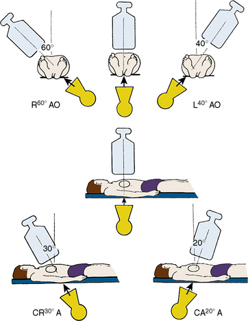
Classical terminology for angiographic projections with regard to left and right anterior oblique, cranial and caudal angulation, and lateral projections remains as defined in previous discussions of diagnostic coronary angiography (see The Cardiac Catheterization Handbook, 5th edition, Chapter 4).
Common Angiographic Views for Angioplasty
The routine coronary angiographic views described below should include those that best visualize the origin and course of the major vessels and their branches in at least two different (preferably orthogonal) projections. Naturally, there is a wide variation in coronary anatomy, and appropriately modified views will need to be individualized. The nomenclature for angiographic views is described in Chapter 4 of The Cardiac Catheterization Handbook, 5th edition, but will be reviewed briefly here, emphasizing the interventionalist’s thinking.
Position for Anteroposterior Imaging
The image intensifier is directly over the patient, with the beam perpendicular to the patient lying flat on the x-ray table (Figs. 3-1, 3-2). The anteroposterior (AP) view or shallow right anterior oblique (RAO) displays the left main coronary artery in its entire perpendicular length. In this view, the branches of the left anterior descending (LAD) and left circumflex coronary arteries branches overlap. Slight RAO or left anterior oblique (LAO) angulation may be necessary to clear the density of the vertebrae and the catheter shaft in the thoracic descending aorta. In patients with acute coronary syndromes, this view will exclude left main stenosis, which can preclude or complicate PCI. The AP cranial view is excellent for visualizing the LAD with septals moving to the left (on screen) and diagonals to the right, helping wire placement.
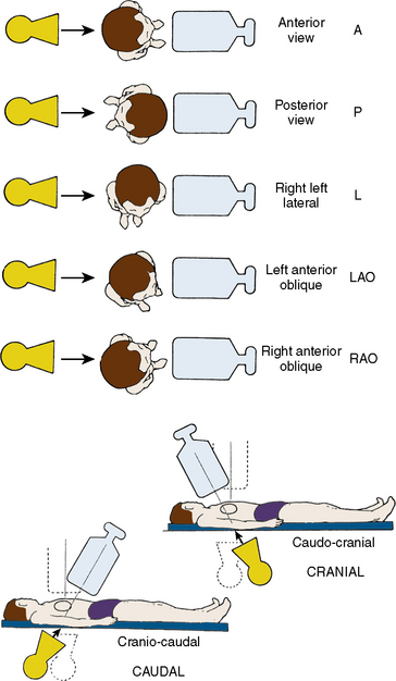
Position for Left Anterior Oblique Imaging
In the LAO position, the image intensifier is to the left side of the patient. The LAO/cranial view also shows the left main coronary artery (slightly foreshortened), LAD, and diagonal branches. Septal and diagonal branches are separated clearly. The circumflex and marginals are foreshortened and overlapped. Deep inspiration will move the density of the diaphragm out of the field. The LAO angle should be set so that the course of the LAD is parallel to the spine and stays in the “lucent wedge” bordered by the spine and the curve of the diaphragm. Cranial angulation tilts the left main coronary artery down and permits view of the LAD/circumflex bifurcation (Fig. 3-3). Too steep an LAO/cranial angulation or shallow inspiration produces considerable overlapping with the diaphragm and liver, degrading the image.
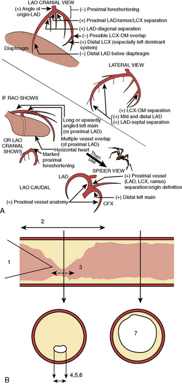
The LAO/caudal view (“spider” view; Fig. 3-3) shows a foreshortened left main coronary artery and the bifurcation of the circumflex and LAD. Proximal and mid portions of the circumflex and the origins of obtuse marginal branches are usually seen excellently. Poor image quality may be due to overlapping of diaphragm and spine. The LAD is considerably foreshortened in this view.
Angulations for Saphenous Bypass Grafts
Coronary artery saphenous vein grafts are visualized in at least two views (LAO and RAO). It is important to show the aortic anastomosis, the body of the graft, and the distal anastomosis. The distal runoff and continued flow or collateral channels are also critical. The graft vessel anastomosis is best seen in the view that depicts the native vessel best. A general strategy for graft angiography is to perform the standard views while assessing the vessel key views for specific coronary artery segments (Table 3-1) to determine the need for contingency views or an alteration/addition of special views. Therefore, the graft views can be summarized as follows:
1. RCA graft: LAO cranial/RAO and lateral
2. LAD graft (or internal mammary artery): lateral, RAO cranial, LAO cranial, and AP (the lateral view is especially useful to visualize the anastomosis to the LAD)
3. Circumflex (and obtuse marginals) grafts: LAO and RAO caudal.
Table 3-1 Recommended “Key” Angiographic Views for Specific Coronary Artery Segments
| Coronary Segment | Origin/Bifurcation | Course/Body |
|---|---|---|
| Left main | AP | AP |
| LAO cranial | LAO cranial | |
| LAO caudal* | ||
| Proximal LAD | LAO cranial | LAO cranial |
| RAO caudal | RAO caudal | |
| Mid LAD | LAD cranial | |
| RAO cranial | ||
| Lateral | ||
| Distal LAD | AP | |
| RAO cranial | ||
| Lateral | ||
| Diagonal | LAO cranial RAO cranial |
RAO cranial, caudal, or straight |
| Proximal circumflex | RAO caudal | LAO caudal |
| LAO caudal | ||
| Intermediate | RAO caudal | RAO caudal |
| LAO caudal | Lateral | |
| Obtuse marginal | RAO caudal | RAO caudal |
| LAO caudal | ||
| RAO cranial (distal marginals) | ||
| Proximal RCA | LAO | |
| Lateral | ||
| Mid RCA | LAO | LAO |
| Lateral | Lateral | |
| RAO | RAO | |
| Distal RCA | LAO cranial | LAO cranial |
| Lateral | Lateral | |
| PDA | LAO cranial | RAO |
| Posterolateral | LAO cranial | RAO cranial |
| RAO cranial | RAO cranial |
AP, anteroposterior; LAD, left anterior descending; LAO, left anterior oblique; PDA, posterior descending artery (from RCA); RAO, right anterior oblique; RCA, right coronary artery.
From Kern MJ, ed. The cardiac catheterization handbook, 2nd ed. St Louis, MO: Mosby, 1995: 286.
Techniques for Coronary Arteriography
Power Injection Versus Hand Injection for Coronary Arteriography
• Right coronary artery: 6 mL at 2–3 mL/sec; maximum pressure 450 psi
• Left coronary artery: 10 mL at 4–6 mL/sec; maximum pressure 450 psi
Angiographic TIMI Classification of Blood Flow
Thrombolysis in myocardial infarction (TIMI) flow grading has been used to assess, in a qualitative fashion, the degree of restored perfusion achieved after thrombolysis or angioplasty in patients with acute myocardial infarction. Table 3-2 provides descriptions used to assign TIMI flow grades.
Table 3-2 Thrombolysis in Myocardial Infarction (TIMI) Flow: Grade and Blush Scores
| TIMI Flow Grade | Description |
|---|---|
| Grade 3 (complete reperfusion) | Anterograde flow into the terminal coronary artery segment through a stenosis is as prompt as anterograde flow into a comparable segment proximal to the stenosis. Contrast material clears as rapidly from the distal segment as from an uninvolved, more proximal segment. |
| Grade 2 (partial reperfusion) | Contrast material flows through the stenosis to opacify the terminal artery segment. However, contrast enters the terminal segment perceptibly more slowly than more proximal segments. Alternatively, contrast material clears from a segment distal to a stenosis noticeably more slowly than from a comparable segment not preceded by a significant stenosis. |
| Grade 1 (penetration with minimal perfusion) | A small amount of contrast flows through the stenosis but fails to fully opacify the artery beyond. |
| Grade 0 (no perfusion) | There is no contrast flow through the stenosis. |
| Myocardial Blush Grade | |
|
0 No myocardial blush or contrast density. Myocardial blush persisted (“staining”). 1 Minimal myocardial blush or contrast density. 2 Moderate myocardial blush or contrast density but less than that obtained during angiography of a contralateral or ipsilateral noninfarct-related coronary artery. 3 Normal myocardial blush or contrast density, comparable with that obtained during angiography of a contralateral or ipsilateral noninfarct-related coronary artery. |
|
Modified from Sheehan F, Braunwald E, Canner P, et al. The effect of intravenous thrombolytic therapy on left ventricular function: a report on tissue-type plasminogen activator and streptokinase from the Thrombolysis in Myocardial Infarction (TIMI) Phase I Trial. Circulation 1987;72:817–829.
Classification of Distal Angiographic Contrast Runoff
The distal runoff is classified into four stages (also known as TIMI grade):
Angiographic Classification of Collateral Flow
Assessment of Coronary Stenoses
1. Minimal or mild CAD, narrowings < 50%
2. Moderate, stenosis between 50% and 75%
Technical note: Stenosis anatomy should not be confused with abnormal physiology (flow) and ischemia, especially for lesions 40% to 70% narrowed. For nonquantitative reports, the length of a stenosis is simply mentioned (e.g., LAD proximal segment stenosis diameter 25%, long or short). Other features of the coronary lesion may not be appreciated by angiography and require IVUS imaging. Anatomic factors producing resistance to coronary flow include factors producing resistance to flow across a coronary stenosis, such as entrance angle, length of disease, length of stenosis, minimal lumen diameter, minimal lumen area, eccentricity of lumen, area of reference vessel segment, and viscosity (Fig. 3-3B).
Coronary Lesion Descriptions for Angioplasty
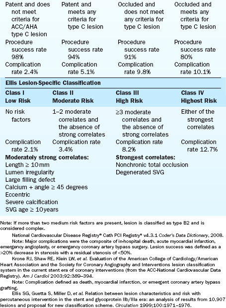
There are at least three major classifications of lesion severity (Table 3-3). These classifications were derived from large studies in which the characteristics of the lesions were associated with different clinical outcomes of the techniques and times of the study. These are helpful to assess risk for adverse cardiac events in the performance of PCI.
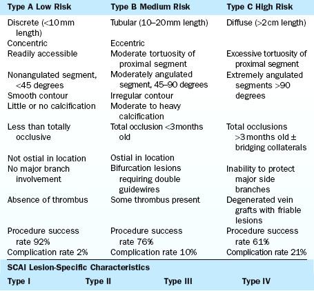
General characteristics of the artery proximal to the lesion dilated are as follows:
Angiographic characteristics of the dilated target lesion are as follows:
3. Arrangement of the lesion(s)
Use of the SYNTAX Score to Describe PCI Risk Versus CABG
The SYNTAX score is the sum of the points assigned to each individual lesion identified in the coronary tree with >50% diameter narrowing in vessels >1.5 mm diameter. The coronary tree is divided into 16 segments according to the AHA classification (Fig. 3-4). Each segment is given a score of 1 or 2 based on the presence of disease; this score is then weighted based on a chart, with values ranging from 3.5 for the proximal LAD to 5.0 for left main, and 0.5 for smaller branches. The branches <1.5 mm in diameter, despite having severe lesions, are not included in the SYNTAX score. The percent diameter stenosis is not a consideration in the SYNTAX score—only the presence of a stenosis from 50% to 99% diameter, < 50% diameter narrowing, or the total occlusion. A multiplication factor of 2 is used for non-occlusive lesions and 5 is used for occlusive lesions, reflecting the difficulty of PCI.
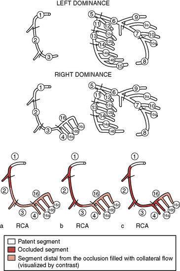
Figure 3-4 SYNTAX diagram. Definition of the coronary tree segments.
1. RCA proximal: From the ostium to one half the distance to the acute margin of the heart.
2. RCA mid: From the end of first segment to acute margin of heart.
3. RCA distal: From the acute margin of the heart to the origin of the posterior descending artery.
4. Posterior descending artery: Running in the posterior interventricular groove.
16. Posterolateral branch from RCA: Posterolateral branch originating from the distal coronary artery distal to the crux.
16a. Posterolateral branch from RCA: First posterolateral branch from segment 16.
16b. Posterolateral branch from RCA: Second posterolateral branch from segment 16.
16c. Posterolateral branch from RCA: Third posterolateral branch from segment 16.
5. Left main: From the ostium of the LCA through bifurcation into left anterior descending and left circumflex branches.
6. LAD proximal: Proximal to and including first major septal branch.
7. LAD mid: LAD immediately distal to origin of first septal branch and extending to the point where LAD forms an angle (RAO view). If this angle is not identifiable, this segment ends at one half the distance from the first septal to the apex of the heart.
8. LAD apical: Terminal portion of LAD, beginning at the end of previous segment and extending to or beyond the apex.
9. First diagonal: The first diagonal originating from segment 6 or 7.
9a. First diagonal a: Additional first diagonal originating from segment 6 or 7, before segment 8.
10. Second diagonal: Originating from segment 8 or the transition between segments 7 and 8.
10a. Second diagonal a: Additional second diagonal originating from segment 8.
11. Proximal circumflex artery: Main stem of circumflex from its origin of left main and including origin of first obtuse marginal branch.
12. Intermediate/anterolateral artery: Branch from trifurcating left main other than proximal LAD or LCX. It belongs to the circumflex territory.
12a. Obtuse marginal a: First side branch of circumflex running in general to the area of obtuse margin of the heart.
12b. Obtuse marginal b: Second additional branch of circumflex running in the same direction as 12.
13. Distal circumflex artery: The stem of the circumflex distal to the origin of the most distal obtuse marginal branch, and running along the posterior left atrioventricular groove. Caliber may be small or artery absent.
14. Left posterolateral: Running to the posterolateral surface of the left ventricle. May be absent or a division of obtuse marginal branch.
14a. Left posterolateral a: Distal from 14 and running in the same direction.
14b. Left posterolateral b: Distal from 14 and 14 a and running in the same direction.
15. Posterior descending: Most distal part of dominant left circumflex when present. It gives origin to septal branches. When this artery is present, segment 4 is usually absent.
(Adapted from Sianos G, Morel MA, Kappetein AP, et al. The SYNTAX score: an angiographic tool grading the complexity of coronary artery disease. EuroIntervention 2005;1:219–227.) LAD, left anterior descending; LCX, left circumflex; RAO, right anterior oblique; RCA, right coronary artery.
Further characterization of the lesions adds points. For example, a total occlusion duration >3 months, a blunt stump, a bridging collateral image, the first segment visible beyond the total occlusion, and a side branch >1.5 diameter all receive 1 point. For trifurcations, one diseased segment gets 3 points, two diseased segments get 4 points, three diseased segments get 5 points, and four disease segments get 6 points. For bifurcation lesions, 1 point is given for types a, b, and c; 2 points are given for types d, e, f, and g; and 1 point is given for an angulation >70 degrees. Additionally, an aorto-ostial lesion is worth 1 point, severe tortuosity of vessel is worth 2 points, lesion length >20 mm is worth 1 point, heavy calcification is worth 2 points, thrombus is worth 1 point, and diffuse disease or small vessel is at 1 point per segment involvement. For multiple lesions, less than three reference vessel diameters apart, these are scored as a single lesion. However, at distance greater than three vessel diameters, these are considered separate lesions. The types of bifurcations are shown in Figure 3-5. Segments in which bifurcations are evaluated are those involving the proximal LAD and left main, the mid LAD, the proximal circumflex, mid circumflex, and crux of the RCA. With regard to trifurcation lesions, these also are additive in number of segments involved. The SYNTAX score algorithm then sums each of these features for a total SYNTAX score. Table 3-4 summarizes the SYNTAX grade categories. A computer algorithm is then queried and a summed value is produced.
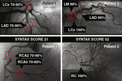
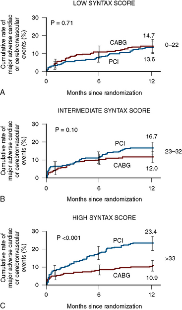
The SYNTAX score is a useful differentiator for the outcome of patients undergoing three-vessel PCI. In Figure 3-5, examples of the types of SYNTAX score are provided on figures from the original paper. The patients with the highest scores have the highest risk and the lowest scores, the lowest risk. The SYNTAX scores can be divided into three tertiles. The high scores indicate complex conditions and represent greatest risks to patients undergoing PCI. High scores have the worst prognosis for revascularization with PCI compared to CABG surgery. Equivalent or superior outcomes for percutaneous intervention were noted in comparison to CABG surgery for patients in the lowest two tertiles (Fig. 3-6). The best discriminating feature of the SYNTAX score was between the lowest and highest tertiles of grading.
Problems and Solutions in the Interpretation of Coronary Angiograms
The basic issues regarding angiography are described in detail in Chapter 4 of The Cardiac Catheterization Handbook, 5th edition. This section briefly directs our attention to these same issues specifically directed at the PCI procedure.
Angiography for PCI of the left main coronary artery is straightforward for aorto-ostial and mid-body left main lesions but requires demonstration of the LAD/CFX ostia in cases of distal left main stenosis. Optimal views to identify the left main coronary artery remain the same as for those during diagnostic studies, with a shallow RAO with cranial or caudal angulation often providing an excellent view. In addition, complementary LAO caudal view (spider view) will display the left main artery in an orthogonal projection. An additional problem is the appreciation of the hemodynamically significance of the left main stenosis especially when the angiographic narrowing is of questionable severity. For this situation, fractional flow reserve (FFR) measurement can provide the hemodynamic severity with a value of > 0.80 having a low 5-year major adverse cardiac event rate. Some operators prefer IVUS before performing revascularization (see Chapter 13).
A discussion of the angiography of anomalous coronary arteries is provided in Chapter 4 of The Cardiac Catheterization Handbook, 5th edition. PCI for these arteries is performed in a routine fashion once stable guide catheter position is achieved.
Radiation Exposure During PCI
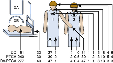
Coronary angioplasty will deliver greater x-ray exposure than diagnostic studies because of the more complicated and time-consuming nature of the procedure. Previous studies have demonstrated that operator exposure is 93% greater for angioplasty than for routine diagnostic coronary angiography. This increase is due to longer fluoroscopy times in angioplasty without corresponding longer cineradiography times. Because of the angled projections used in coronary angioplasty, increased x-ray exposure may be present. The scattered x-ray dose has been reported to be four times higher with angioplasty than with diagnostic cardiac catheterization (Fig. 3-7).
Fluoroscopy Times
A study by Pattee et al. (1993) of radiation risk to patients from coronary angioplasty indicated that radiation doses varied considerably during the procedure because of large differences in exposure times. Skin exposures estimated for PCI are, on average, higher than for other x-ray procedures and the cancer mortality risk does not exceed the mortality risk of bypass surgery (Table 3-5). Good professional practice requires maximal benefit-to-risk ratio for angioplasty procedures employing high-dose fluoroscopy or cineradiography. Device specific procedure times may be longer than routine stent placement (Table 3-6).
Table 3-5 Organ Doses and Risks of Cancer Mortality for an Average Coronary Angioplasty Procedure
| Organ | Organ Dose (cGy)* | Cancer Risk Mortality (× 10− 6) |
|---|---|---|
| Red bone marrow | 2.29 | 92 |
| Bone (surfaces) | 2.29 | 9.2 |
| Lung | 9.35 | 636 |
| Thyroid | 0.99 | 5.9 |
| Breast (women) | 4.89 | 157 |
| Total risk | ||
| Men | 743 | |
| Women | 899 |
From Pattee PL, Johns PC, Chambers RJ. Radiation risk to patients from percutaneous transluminal coronary angioplasty. J Am Coll Cardiol 1993;22:1044–1051.
Table 3-6 Estimated Radiation Entrance Exposure of Patients Using Phantom Model Data
| Procedure | Fluoroscopy (R) | Cine (R) |
|---|---|---|
| Isolated balloon angioplasty | 43 | 25 |
| Isolated directional coronary atherectomy | 32 | 23 |
| Directional coronary atherectomy + balloon angioplasty | 66 | 29 |
| Isolated laser coronary angioplasty | 45 | 18 |
| Laser coronary angioplasty + balloon angioplasty | 57 | 27 |
| Elective stenting | 52 | 27 |
| Emergency stenting | 96 | 41 |
R, RAD.
From Federman J, Bell MR, Wondrow MA, et al. Does the use of new intracoronary interventional devices prolong radiation exposure in the cardiac catheterization laboratory? J Am Coll Cardiol 1994;23:347–357.
Angulated views increase radiation exposure. Left anterior oblique views produce 2.6 to 6.1 times the dose of radiation for the operator of equivalently angled RAO views (Table 3-7). Steeper LAO views also increased operator dose. LAO 90 degrees produces 8 times the dose of LAO 60 degrees and 3 times the dose of LAO 30 degrees. Fluoroscopy produced more radiation than cine during angioplasty, by a factor of 6:1. Reducing the steepness of angulation reduces operator radiation dosage.
Table 3-7 Radiation Dose and Angulation
| View | Dose (Relative Increase) |
|---|---|
| Image Intensifier Position | |
| RAO 30–60 degrees | 1 |
| LAO 30–60 degrees | 2.6–6.1 |
| Increasing Angulation | |
| LAO 30 degrees | 1 |
| LAO 60 degrees | 3 |
| LAO 90 degrees | 9 |
LAO, left anterior oblique; RAO, right anterior oblique.
Peripheral Vascular Angiography (See also Chapter 14)
Lower Extremity Angiography
Angiography of the lower extremities is part of peripheral vascular interventions, discussed in Chapter 11. Based on clinical signs and symptoms of arterial insufficiency to the legs, suspected obstructions of the vessel are initially screened with noninvasive studies (i.e., ankle brachial index). Angiography is performed with small-diameter (5 F) catheters and reduced contrast volumes (10–20 mL over 1–2 sec) which are injected, panning down and following the artery course to the most distal locations. Angulated views may be necessary to open bifurcations and overlying vessels that obscure the vessel origin. Panning down to the ankle must be tested before obtaining final views. Digital subtraction techniques are commonly available in modern laboratories. Nonionic contrast agents are less painful than ionic media for peripheral angiography.
The area most frequently involved in peripheral atherosclerotic disease is the distal superficial femoral artery at the abductor canal (Fig. 3-7). The calf (tibial), and knee (popliteal) arteries are the next most commonly involved vessels after the superficial femoral artery. Disease in the deep femoral artery (femoral profunda) is rare. Pathways of collateralization are often rich and varied in patients with chronic distal femoral artery disease, especially in total occlusion of the superficial femoral artery that reconstitutes at or below the knee, close to the branching trifurcation of the tibial and deep peroneal arteries. Determining the level of reconstitution of collateralized vessels and distal runoff is crucial in determining the feasibility of revascularization. Magnified images focusing on the area of interest are frequently needed.
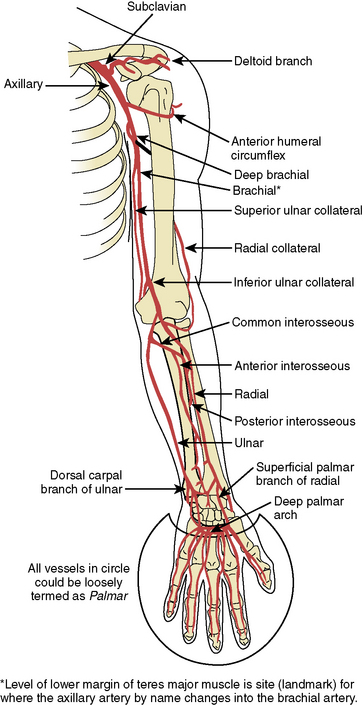
Diagrams and nomenclature for additional angiographic studies are shown in Figures 3-8 through 3-12; see also Chapter 11.
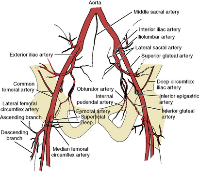
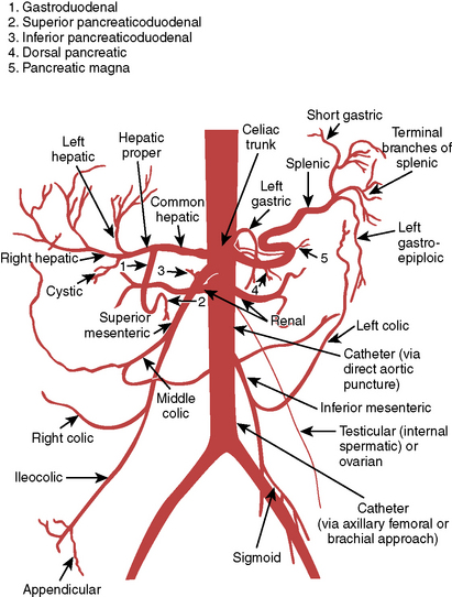
Figure 3-8 Pelvic and proximal femoral arterial branches.
(From Johnsrude IS, Jackson DC, Dunnick NR. A practical approach to angiography, 2nd ed. Boston: Little, Brown, 1987.)
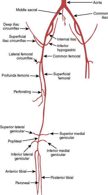
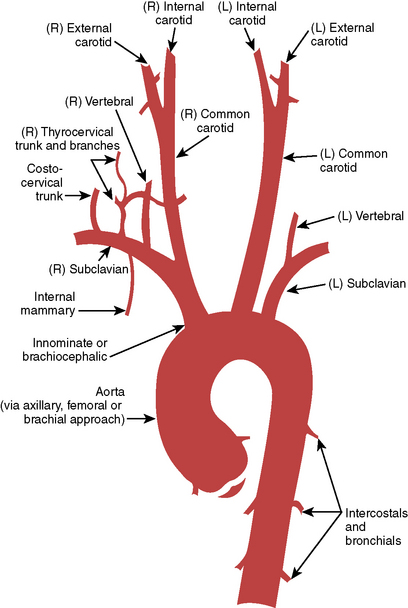
Figure 3-10 Ascending aorta and head and neck vessels.
(From Medical Learning Incorporated, with permission.)
Pacemakers During PCI
Indications
1. Previously demonstrated high-degree conduction block
2. Symptomatic bradycardia (after contrast or angiography of RCA)
3. Acute myocardial infarction with trifascicular block
4. Prophylactic use for rotational atherectomy and thrombectomy procedures, especially involving the RCA
5. Transluminal alcohol septal artery ablation in hypertrophic obstructive cardiomyopathy (HOCM) patients
Balter S., Moses J. Managing patient dose in interventional cardiology. Catheter Cardiovasc Interv. 2007;70:244–249.
Chida K., Fuda K., Saito H., et al. Patient skin dose in cardiac interventional procedures: conventional fluoroscopy versus pulsed fluoroscopy. Catheter Cardiovasc Interv. 2007;69:115–121.
Gibson C.M., Cannon C.P., Daley W.L., et al. TIMI frame count: a quantitative method of assessing coronary artery flow. Circulation. 1996;93:879–888.
Green N.E., Chen S.Y.J., Hansgen A.R., et al. Angiographic views used for percutaneous coronary interventions: a three-dimensional analysis of physician-determined vs. computer-generated views. Catheter Cardiovasc Interv. 2005;64:451–459.
Hirshfeld J.W.Jr, Balter S., Brinker J.A., et al. ACCF/AHA/HRS/SCAI clinical competence statement on physician knowledge to optimize patient safety and image quality in fluoroscopically guided invasive cardiovascular procedures, A report of the American College of Cardiology Foundation/American Heart Association/American College of Physicians Task Force on Clinical Competence and Training. J Am Coll Cardiol. 2004;44:2259–2282.
Katritsis D., Efstathopoulos E., Betsou S., et al. Radiation exposure of patients and coronary arteries in the stent era: a prospective study. Catheter Cardiovasc Interv. 2000;51:259–264.
Kaul P., Medvedev S., Hohmann S.F., et al. Ionizing radiation exposure to patients admitted with acute myocardial infarction in the United States. Circulation. 2010;122:2160–2169.
Kern M. The cardiac catheterization handbook, 5th ed. Philadelphia: Saunders; 2011.
Koenig T.R., Wolff D., Metter F.A., et al. Skin injuries from fluoroscopically guided procedures: part I, characteristics of radiation injury. AJR. 2001;177:3–11.
Mahesh M. Fluoroscopy: patient radiation exposure issues. Radiographics. 2001;21:1033–1045.
Pattee P.L., Johns P.C., Chamber R.J. Radiation risk to patients from percutaneous coronary angioplasty. J Am Coll Cardiol. 1993;22:1044–1051.
Serruys P.W., Morice M.C., Kappetein A.P., et al. Percutaneous coronary intervention versus coronary-artery bypass grafting for severe coronary artery disease. (The SYNTAX Trial). N Engl J Med. 2009;360:961–972.
Sianos G., Morel M.A., Kappetein A.P., et al. The SYNTAX score: an angiographic tool grading the complexity of coronary artery disease. EuroIntervention. 2005;1:219–227.
Suzuki S., Furui S., Isshiki T., et al. Methods to reduce patients’ maximum skin dose during percutaneous coronary intervention for chronic total occlusion. Catheter Cardiovasc Interv. 2008;71:792–798.
Tobis J., Azarbal B., Slavin L. Assessment of intermediate severity coronary lesions in the catheterization laboratory. J Am Coll Cardiol. 2007;49:839–848.
Valgimigli M., Serruys P.W., Tsuchida K., et al. Cyphering the complexity of coronary artery disease using the SYNTAX score to predict clinical outcome in patients with three vessel lumen obstruction Undergoing Percutaneous Coronary Intervention. Am J Cardiol. 2001;99(8):1072–1081.
White C.J., Jaff M.R., Haskal Z.J., et al. Indications for renal angiography at the time of coronary angiography: a science advisory from the American Heart Association Committee on Diagnostic and Interventional Cardiac Catheterization, Council on Clinical Cardiology, and the Councils on Cardiovascular Radiology and Intervention and on Kidney in Cardiovascular Disease. Circulation. 2006;114:1892–1895.
[/level-membership-for-cardiovascular-category][not-level-membership-for-cardiovascular-category]
3 Angiography for Percutaneous Coronary Interventions
1. Establish the relationship of coronary ostium to aorta for guide catheter selection.
2. Verify target vessel, pathway, and angle of entry.
3. Confirm lesion length and morphology using additional angulated views eliminating vessel overlap.
4. Separate associated side branches and degree of ostial atherosclerosis.
5. Visualize distribution of collateral supply.
6. Determine the true (maximally vasodilated) diameter of the coronary artery at the target site.
Classical terminology for angiographic projections with regard to left and right anterior oblique, cranial and caudal angulation, and lateral projections remains as defined in previous discussions of diagnostic coronary angiography (see The Cardiac Catheterization Handbook, 5th edition, Chapter 4).
Common Angiographic Views for Angioplasty
The routine coronary angiographic views described below should include those that best visualize the origin and course of the major vessels and their branches in at least two different (preferably orthogonal) projections. Naturally, there is a wide variation in coronary anatomy, and appropriately modified views will need to be individualized. The nomenclature for angiographic views is described in Chapter 4 of The Cardiac Catheterization Handbook, 5th edition, but will be reviewed briefly here, emphasizing the interventionalist’s thinking.
Position for Anteroposterior Imaging
The image intensifier is directly over the patient, with the beam perpendicular to the patient lying flat on the x-ray table (Figs. 3-1, 3-2). The anteroposterior (AP) view or shallow right anterior oblique (RAO) displays the left main coronary artery in its entire perpendicular length. In this view, the branches of the left anterior descending (LAD) and left circumflex coronary arteries branches overlap. Slight RAO or left anterior oblique (LAO) angulation may be necessary to clear the density of the vertebrae and the catheter shaft in the thoracic descending aorta. In patients with acute coronary syndromes, this view will exclude left main stenosis, which can preclude or complicate PCI. The AP cranial view is excellent for visualizing the LAD with septals moving to the left (on screen) and diagonals to the right, helping wire placement.
Position for Left Anterior Oblique Imaging
In the LAO position, the image intensifier is to the left side of the patient. The LAO/cranial view also shows the left main coronary artery (slightly foreshortened), LAD, and diagonal branches. Septal and diagonal branches are separated clearly. The circumflex and marginals are foreshortened and overlapped. Deep inspiration will move the density of the diaphragm out of the field. The LAO angle should be set so that the course of the LAD is parallel to the spine and stays in the “lucent wedge” bordered by the spine and the curve of the diaphragm. Cranial angulation tilts the left main coronary artery down and permits view of the LAD/circumflex bifurcation (Fig. 3-3). Too steep an LAO/cranial angulation or shallow inspiration produces considerable overlapping with the diaphragm and liver, degrading the image.
The LAO/caudal view (“spider” view; Fig. 3-3) shows a foreshortened left main coronary artery and the bifurcation of the circumflex and LAD. Proximal and mid portions of the circumflex and the origins of obtuse marginal branches are usually seen excellently. Poor image quality may be due to overlapping of diaphragm and spine. The LAD is considerably foreshortened in this view.
Angulations for Saphenous Bypass Grafts
Coronary artery saphenous vein grafts are visualized in at least two views (LAO and RAO). It is important to show the aortic anastomosis, the body of the graft, and the distal anastomosis. The distal runoff and continued flow or collateral channels are also critical. The graft vessel anastomosis is best seen in the view that depicts the native vessel best. A general strategy for graft angiography is to perform the standard views while assessing the vessel key views for specific coronary artery segments (Table 3-1) to determine the need for contingency views or an alteration/addition of special views. Therefore, the graft views can be summarized as follows:
1. RCA graft: LAO cranial/RAO and lateral
2. LAD graft (or internal mammary artery): lateral, RAO cranial, LAO cranial, and AP (the lateral view is especially useful to visualize the anastomosis to the LAD)
3. Circumflex (and obtuse marginals) grafts: LAO and RAO caudal.
Table 3-1 Recommended “Key” Angiographic Views for Specific Coronary Artery Segments
| Coronary Segment | Origin/Bifurcation | Course/Body |
|---|---|---|
| Left main | AP | AP |
| LAO cranial | LAO cranial | |
| LAO caudal* | ||
| Proximal LAD | LAO cranial | LAO cranial |
| RAO caudal | RAO caudal | |
| Mid LAD | LAD cranial | |
| RAO cranial | ||
| Lateral | ||
| Distal LAD | AP | |
| RAO cranial | ||
| Lateral | ||
| Diagonal | LAO cranial RAO cranial |
RAO cranial, caudal, or straight |
| Proximal circumflex | RAO caudal | LAO caudal |
| LAO caudal | ||
| Intermediate | RAO caudal | RAO caudal |
| LAO caudal | Lateral | |
| Obtuse marginal | RAO caudal | RAO caudal |
| LAO caudal | ||
| RAO cranial (distal marginals) | ||
| Proximal RCA | LAO | |
| Lateral | ||
| Mid RCA | LAO | LAO |
| Lateral | Lateral | |
| RAO | RAO | |
| Distal RCA | LAO cranial | LAO cranial |
| Lateral | Lateral | |
| PDA | LAO cranial | RAO |
| Posterolateral | LAO cranial | RAO cranial |
| RAO cranial | RAO cranial |
AP, anteroposterior; LAD, left anterior descending; LAO, left anterior oblique; PDA, posterior descending artery (from RCA); RAO, right anterior oblique; RCA, right coronary artery.
From Kern MJ, ed. The cardiac catheterization handbook, 2nd ed. St Louis, MO: Mosby, 1995: 286.
Techniques for Coronary Arteriography
Power Injection Versus Hand Injection for Coronary Arteriography
• Right coronary artery: 6 mL at 2–3 mL/sec; maximum pressure 450 psi
• Left coronary artery: 10 mL at 4–6 mL/sec; maximum pressure 450 psi
Angiographic TIMI Classification of Blood Flow
Thrombolysis in myocardial infarction (TIMI) flow grading has been used to assess, in a qualitative fashion, the degree of restored perfusion achieved after thrombolysis or angioplasty in patients with acute myocardial infarction. Table 3-2 provides descriptions used to assign TIMI flow grades.
Table 3-2 Thrombolysis in Myocardial Infarction (TIMI) Flow: Grade and Blush Scores
| TIMI Flow Grade | Description |
|---|---|
| Grade 3 (complete reperfusion) | Anterograde flow into the terminal coronary artery segment through a stenosis is as prompt as anterograde flow into a comparable segment proximal to the stenosis. Contrast material clears as rapidly from the distal segment as from an uninvolved, more proximal segment. |
| Grade 2 (partial reperfusion) | Contrast material flows through the stenosis to opacify the terminal artery segment. However, contrast enters the terminal segment perceptibly more slowly than more proximal segments. Alternatively, contrast material clears from a segment distal to a stenosis noticeably more slowly than from a comparable segment not preceded by a significant stenosis. |
| Grade 1 (penetration with minimal perfusion) | A small amount of contrast flows through the stenosis but fails to fully opacify the artery beyond. |
| Grade 0 (no perfusion) | There is no contrast flow through the stenosis. |
| Myocardial Blush Grade | |
|
0 No myocardial blush or contrast density. Myocardial blush persisted (“staining”). 1 Minimal myocardial blush or contrast density. 2 Moderate myocardial blush or contrast density but less than that obtained during angiography of a contralateral or ipsilateral noninfarct-related coronary artery. 3 Normal myocardial blush or contrast density, comparable with that obtained during angiography of a contralateral or ipsilateral noninfarct-related coronary artery. |
|
Modified from Sheehan F, Braunwald E, Canner P, et al. The effect of intravenous thrombolytic therapy on left ventricular function: a report on tissue-type plasminogen activator and streptokinase from the Thrombolysis in Myocardial Infarction (TIMI) Phase I Trial. Circulation 1987;72:817–829.
Classification of Distal Angiographic Contrast Runoff
The distal runoff is classified into four stages (also known as TIMI grade):
TIMI Frame Count
1. For the LAD, the distal bifurcation of the LAD artery
2. For the circumflex system, the distal bifurcation of the branch segments with the longest total distance
3. For the RCA, the first branch of the posterolateral artery
[/not-level-membership-for-cardiovascular-category]
