Published on 26/02/2015 by admin
Filed under Cardiovascular
Last modified 22/04/2025
This article have been viewed 2413 times
3 Angiography
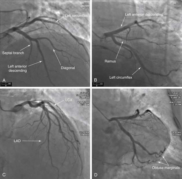
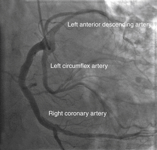
FIGURE 3-1 Left coronary system.
A, A Judkins left 3.5 catheter has been advanced to the LMCA ostium via the right radial approach. This projection is obtained in the AP cranial view. The LMCA arises in the normal location from the left sinus of Valsalva. The LAD travels down toward the bottom of the image. The major branches that arise from this artery are the septal penetrators and the diagonals. The LCX is located across the top of the image and moves toward the right. This view has significant overlap of the circumflex branches, noted by the double density of contrast media. B, The AP caudal projection demonstrates the bifurcation of the LAD and LCX systems and is used to look for ostial stenoses. The LCX gives rise to major branches that are termed obtuse marginals. In this image, a branch occurs between the LAD and LCX, arising from the LMCA. When present, the artery is named the ramus intermediate. C, An AP cranial view of another normal LAD. This image allows better visualization of the mid- and distal LAD. In this patient, the first diagonal is nearly the same size as the LAD. D, Finally, another AP caudal projection demonstrating the bifurcation of the LAD and LCX systems. There is no significant CAD present in this patient. The LCX system is seen as it travels toward the bottom right corner of this image. The LAD is located at the top of the image moving horizontally across.
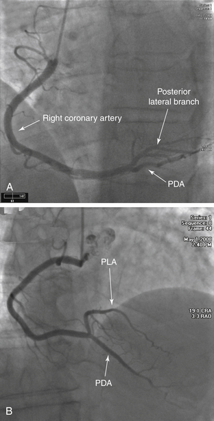
FIGURE 3-2 Right coronary system.
A, A Judkins right 4.0 catheter is placed at the ostium of the RCA, and an angiogram is obtained in the straight LAO projection. No significant disease is noted. This is a right dominant coronary system; the PDA arises from the distal RCA. B, This is an AP cranial view of another RCA. The bifurcation of the posterior descending coronary artery and posterolateral coronary artery is best visualized in this view.
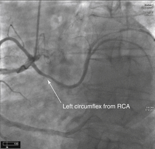
FIGURE 3-3 Anomalous LCX.
Diagnostic cardiac catheterization in a patient with unstable angina. The LCX arises off the right coronary cusp from the same orifice as the RCA (anomalous origin of the LCX).
The most common coronary anomaly is separate ostia of the LCX and LAD arising from the left sinus of Valsalva. This is followed by the LCX arising from the RCA or right sinus of Valsalva.
Most coronary anomalies are clinically silent; however, if the LMCA arises from the pulmonary trunk or aberrantly courses between the great vessels, an increased association with sudden death, myocardial ischemia, and endocarditis is seen.
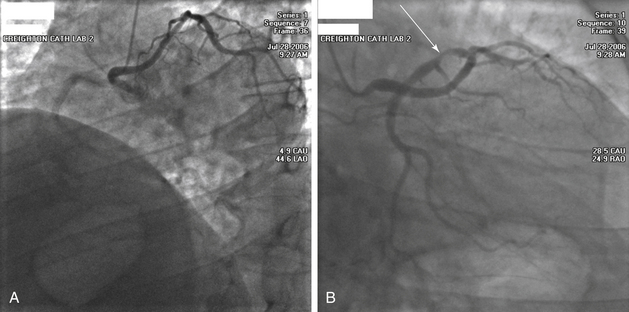
FIGURE 3-4 Anomalous left main from the right coronary cusp. A, This image is obtained in the LAO projection. A Judkins right catheter has been advanced into the aorta from the right radial artery. As contrast medium is injected, there is faint filling of the RCA coming toward the left side of the image. The catheter, however, is in the ostium of the LMCA. The LMCA is anomalous and transverses across the heart muscle and bifurcates into the LAD and LCX. In this view, it appears that the artery courses anterior to the aorta, but further imaging should be performed to confirm this positioning. B, This image is obtained in the RAO projection. This clearly demonstrates that the LMCA is very long and extends to the left ventricular side before it bifurcates. There is severe stenosis of the proximal LCX (arrow).
FIGURE 3-5 Single coronary artery. A Judkins right 4.0 coronary catheter is noted in the right coronary cusp on this LAO projection. As the contrast enters the artery, all three of the major coronary arteries are visualized arising from the same common trunk. The RCA follows the standard course toward the inferior border of the heart. The LCX is located in the middle of the image and travels to the lateral wall of the ventricle. The LAD is toward the back of the image and is recognized secondary to the presence of septal branches. This anomaly is rare, occurring in 0.02% of the population.
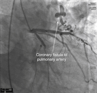
FIGURE 3-6 Coronary artery fistula.
LAO view of the left coronary system during diagnostic catheterization. Note the fistula from the LAD to the PA. This is the most common type of coronary artery fistula. Other connections include from a coronary artery to the right ventricle, right atrium, or coronary sinus.
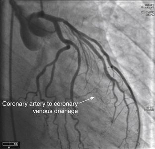
FIGURE 3-7 Coronary artery to coronary venous drainage. A Judkins left 4.0 catheter has been placed in the ostium of the LMCA via the femoral approach. The angiogram is obtained in the RAO caudal projection. As the contrast medium enters the left coronary circulation, staining is noted in the middle of the cardiac silhouette that partially clears with ventricular systole. This is consistent with coronary artery to coronary venous drainage. The coronary venous drainage occurs through the thebesian system directly into the ventricles.
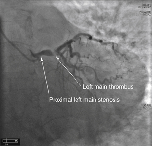
FIGURE 3-8 Left main stenosis with thrombus. A Judkins left 3.5 catheter is placed in the LMCA ostium from the right radial approach. In the AP caudal projection, a lesion is noted at the origin of the LMCA. Comparing the diameter of the vessel proximal to and distal to the lesion, a significant narrowing is noted. The most striking portion of this angiogram is the hazy lucent portion of the artery at the bifurcation of the LAD and LCX, secondary to a large thrombus. In the cine angiograms, the flow into the distal vessels is slightly impaired. An additional thrombus is noted in the mid-LCX. In addition, the RCA is filled late by collaterals, demonstrating that the proximal portion of the artery is likely occluded. The entire coronary circulation is compromised by the thrombus.
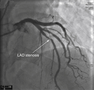
FIGURE 3-9 Left anterior descending artery stenosis. A Judkins left coronary catheter is positioned in the LMCA ostium from the right radial approach. The camera is positioned in the AP cranial projection. In the middle of the frame, a significant flow-limiting stenosis is seen in the mid-LAD. This lesion is located after the bifurcation of the first diagonal branch. Comparing the luminal diameter in the arterial segment proximal to and distal to the lesion, there is an approximate 90% to 99% narrowing of the artery.
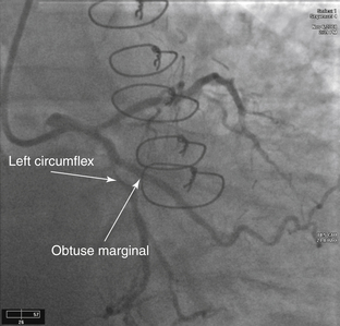
FIGURE 3-10 Left circumflex artery stenosis. This angiogram is obtained via the radial approach in the LAO caudal projection. This view is ideal for separating the ostia of the LAD and LCX. The LAD is the more superior vessel and travels to the left of the image. The LCX is the lower vessel and travels toward the bottom of the image. A 90% to 99% lesion is present in the midportion of the LCX just after the takeoff of the first obtuse marginal branch. The area appears to be slightly more radiolucent than the surrounding vessel. This is an irregular plaque producing significant narrowing.
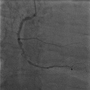
FIGURE 3-11 Right coronary artery stenosis. This angiogram of the RCA is obtained in the straight LAO projection. A severe obstructive lesion is seen in the midsegment of the vessel. The segment of artery distal to the large acute marginal branch is diseased as it enters the area with the severe lesion. The distal vessel is small but relatively free of disease.
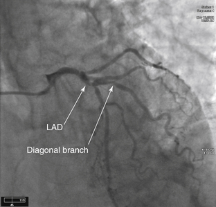
FIGURE 3-12 Left anterior descending/diagonal stenosis. The image has been obtained in the AP cranial projection. In the middle of the frame, a significant stenosis of the LAD involving the bifurcation of a large diagonal branch is seen. This stenosis makes percutaneous intervention more complicated because there is a risk that flow will be compromised within this side branch.
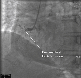
FIGURE 3-13 Total right coronary artery occlusion. A Judkins right 4.0 catheter is positioned at the ostium of the RCA. This image is obtained in the LAO view. The artery is totally occluded proximally. The lesion is said to be in the proximal portion of the vessel because it occurs before the first major acute marginal branch. The mid-RCA is defined as the portion of the artery from the end of the proximal segment to the next major acute marginal branch. The distal RCA is located from the end of the midsegment to the bifurcation of the PDA.
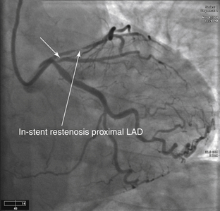
FIGURE 3-14 In-stent restenosis of left anterior descending artery. An XB guiding catheter is present in the LMCA ostium from the radial artery approach. This image was obtained in the AP caudal projection. Before contrast injection, a stent can be visualized in the proximal portion of the LAD. A significant narrowing within the stent is consistent with in-stent restenosis. The LCX is without significant disease. However, there is a significant ostial lesion (short arrow) of the first obtuse marginal branch.
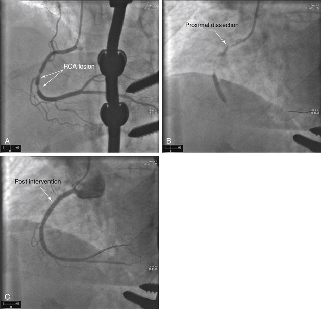
FIGURE 3-15 Right coronary artery stenosis with catheter dissection.
A, Initial angiograms obtained using a diagnostic catheter via the right radial approach demonstrate severe lesions in the midportion of the RCA. B, In the second angiogram in this series, a Judkins right 4.0 guiding catheter is in the ostium of the RCA. A 0.014-inch wire has been advanced through the lesion and into the distal vessel. A balloon is inflated at the site of the original lesion. Note the contrast persistent within the proximal vessel. A type D coronary dissection is noted. This occurs when the guide wire becomes subintimal and then reenters the lumen more distally. The dissection then propagates in a spiral fashion down the arterial wall. C, To prevent further propagation of the dissection and coronary occlusion, the injured site is often covered with a stent, as shown in the final sequence.
Dissections are categorized by NHLBI classification as type A to F. Type A and B dissections can often be managed conservatively, whereas type C through F require additional treatment. Type A dissections demonstrate a small radiolucent area within the coronary lumen during contrast injection but no persistence of contrast in the vessel. Type B dissections show a “parallel” tract or double lumen separated by a radiolucent band during angiography without residual contrast when the injection is completed. A Type C dissection appears with contrast media located outside the coronary lumen. This is termed the extraluminal cap. There is contrast media present after the dye has cleared from the main lumen. Type D dissections are spiral dissections often with contrast staining of the false lumen. Type E dissections appear as new persistent filling defects within the coronary lumen. Type F dissections cause total occlusion of the vessel without distal flow.
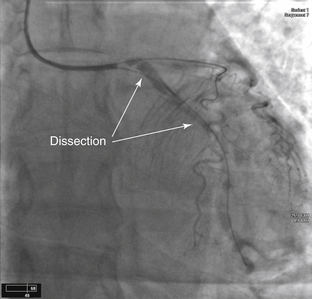
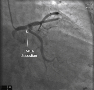
FIGURE 3-16 LMCA and LCX dissection.
An XB guiding catheter is visualized at the ostium of the LMCA. A type E dissection of the LCX was caused by the diagnostic coronary catheter; this dissection propagated proximally to the LMCA. Two wires are present: one in the LAD and the other in the LCX. These wires maintained flow into the distal arterial system. The patient was taken to the operating room for emergent CABG surgery.
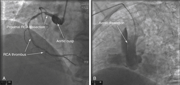
FIGURE 3-17 Aortic cusp/root dissection
A, An Amplatz left guiding catheter is near the ostium of the RCA. A 0.014-inch wire is present in preparation for intervention because significant stenosis and thrombus are present within the vessel. A dissection flap is noted in the proximal artery and likely begins at the ostial-aortic junction. As the angiogram is obtained, contrast enters into the aortic wall and stains the cusp. B, The dissection at the cusp has now propagated superiorly and is involving the proximal portion of the aortic root. This often requires immediate surgical repair, as this is a Stanford class A aortic dissection.
FIGURE 3-18 Left main coronary artery dissection. A catheter is positioned in the LMCA via the right radial approach. The angiogram is obtained in the AP caudal view. Note that prior to injection, contrast material is already present in the artery at the tip of the catheter, suggestive of a coronary artery dissection. As the contrast is injected, the contrast material does not clear from the proximal segment. In addition, a radiolucent line is apparent in the distal portion of the LMCA. This is the dissection flap.
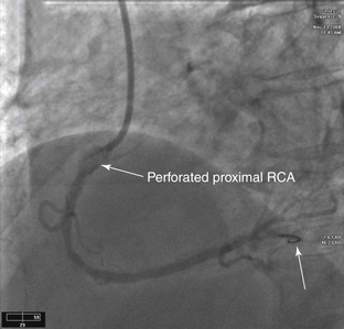
FIGURE 3-19 Right coronary artery perforation with rotational atherectomy device. In this angiogram, intervention is being performed on the RCA. A Judkins right guiding catheter is positioned above the ostium of the RCA. A 0.014-inch wire is present and has been advanced into the distal vessel (arrow). The diagnostic coronary angiogram demonstrated a significant stenosis in the proximal portion of the artery, which was heavily calcified. Due to the heavy calcification, it was determined that debulking of the lesion before stent implantation would improve the result. Debulking of heavily calcified lesions can be done with rotational atherectomy. With a rotational atherectomy device on the wire, several passes are made through the lesion. Afterwards, a repeat angiogram is obtained. The proximal RCA has been perforated and contrast is noted outside the vessel lumen. This is treated using prolonged balloon inflations in the affected segment until the perforation is sealed. In addition, a covered stent may be placed over the perforated segment.
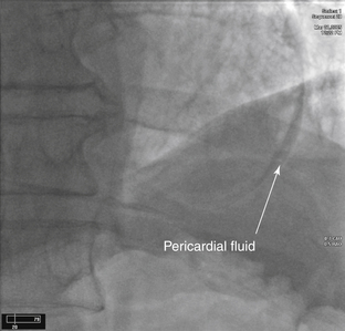
FIGURE 3-20 Coronary perforation with pericardial staining.
This is a postintervention angiogram in the straight AP projection. The patient underwent intervention to the LAD and a wire passed outside the vessel lumen. Contrast can be seen in the pericardial space, indicating that the vessel has been perforated.
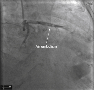
FIGURE 3-21 Air embolism.
A catheter is present in the LMCA via the right radial approach. The image was captured in the RAO caudal projection. The LCX courses down toward the bottom left corner of the image. The LAD travels across the image. The discrete areas of lucency noted in the LAD are air emboli that occurred at the time of contrast injection. The patient is administered high-flow oxygen while the air emboli dissolve.
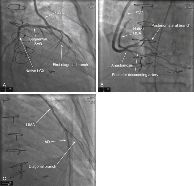
FIGURE 3-22 Coronary artery bypass angiography. A, A Judkins right catheter has been positioned in the ascending aorta from the femoral approach. Notice that this catheter position is higher than would be expected for normal coronary artery origins. Grafts to the left coronary system usually arise from the left side of the aorta, and those to the RCA usually arise from the right side of the aorta. This selective angiogram has been obtained in the RAO caudal view. It demonstrates an SVG that travels from the aorta to the first diagonal branch of the LAD and then in a sequential fashion to the first obtuse marginal branch of the LCX. B, The catheter has now been positioned on the right side of the aorta. Again, the position of the catheter is significantly higher than the normal position of the native coronary arteries. This image was obtained in the AP cranial projection. This SVG is to the distal RCA. The native artery fills in a retrograde fashion up to the area of occlusion. The distal vessels of the right coronary circulation, the PDA and PLA, are well visualized and free of significant disease. C, The catheter has now been advanced into the left subclavian artery and has been positioned at the ostium of the LIMA. This is the preferred bypass conduit to use for the LAD circulation, because the patency of this graft is 90% at 10 years. The angiogram is obtained in the RAO cranial projection. This allows for adequate visualization of the anastomosis of the mammary artery to the coronary artery. Visualizing the anastomosis is important because many times flow-limiting lesions occur at this site.
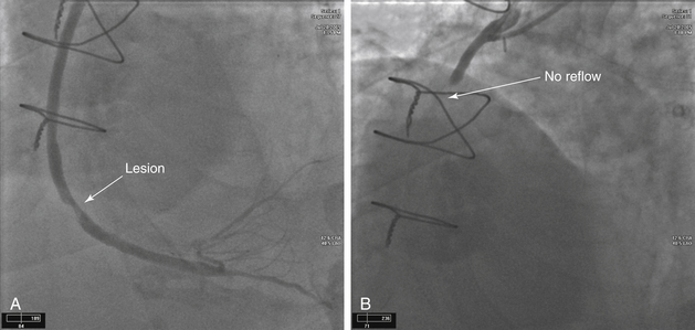
FIGURE 3-23 SVG stenosis and subsequent no reflow.
A, An SVG anastomosed to the distal RCA is shown in this LAO cranial view. Note the significant lesion in the distal portion of the graft. Using a distal protection device, the lesion was dilated and a stent was placed. However, after removal of the guidewire, no reflow was noted. B, No reflow is likely to occur when a large thrombus burden is present or when intervention has been performed on a degenerated SVG. A lack of reflow is caused by distal embolization into the microcirculation. These vessels are too small to be visualized by angiography; however, because there is no outlet for the contrast material, the dye appears to “hang” in the artery. It is treated by intra-arterial injections of vasodilator medications, such as nicardipine and nitroprusside.
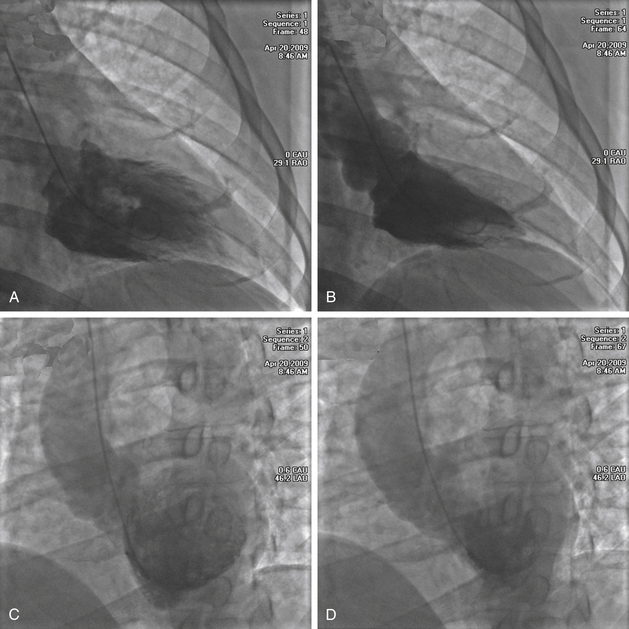
FIGURE 3-24 Left ventriculography. Images obtained in the RAO projection, one in diastole (A) and the other in systole (B). A pigtail catheter has been placed into the LV through the aortic valve. In diastole, the left ventricular cavity is of normal size and becomes significantly smaller in systole. During systole, all of the myocardial segments contract inward and thicken. There are no regional wall motion abnormalities. Images are also often obtained in the LAO projection, diastole (C) and systole (D).
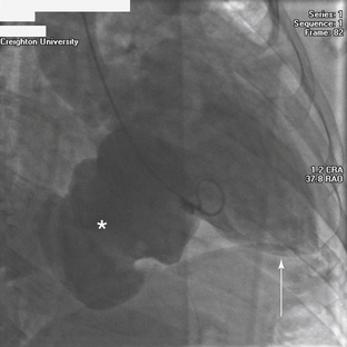
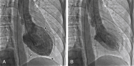
FIGURE 3-25 Giant left ventricular aneurysm. This image is obtained in the RAO projection. A pigtail catheter is in the left ventricular cavity, and contrast medium is injected to visualize the chamber. The apex of the heart is located toward the bottom right edge of the image (arrow). The large mass that appears to be arising from the diaphragmatic wall of the LV, is a large left ventricular aneurysm (asterisk). The aneurysm has a large opening or neck that distinguishes it from a pseudoaneurysm, which has a narrow neck. This is an unusual location for a left ventricular aneurysm. Common locations for these defects are at the apex and in the anterior wall.
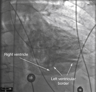
FIGURE 3-26 Post-infarct VSD.
Left ventriculogram in an RAO view demonstrating a VSD, which occurred several days after an anteroseptal MI.
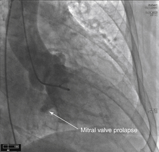
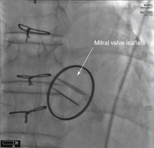
FIGURE 3-27 Mitral valve prolapse.
A pigtail catheter has been placed into the LV via the femoral approach. The ventriculogram has been obtained in the RAO projection. The posterior leaflet of the mitral valve is prolapsing into the left atrium. Mild mitral regurgitation is noted.
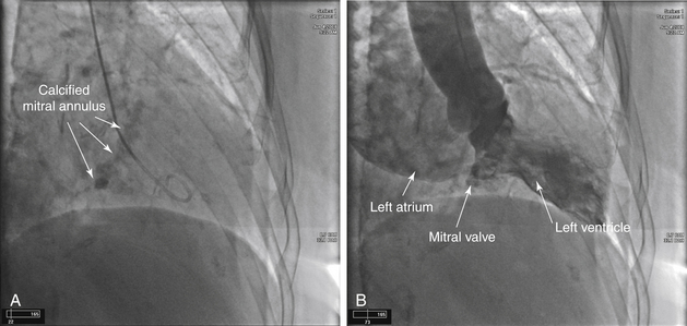
FIGURE 3-28 Mitral annular calcification and mitral regurgitation
A, A pigtail catheter has been placed into the LV via the right radial approach. The large area of calcification in the center of the image represents the annulus of the mitral valve. B, As contrast is injected into the ventricle, a significant amount of dye is passing back through the mitral valve into the left atrium indicating moderate to severe mitral regurgitation. The left atrium is severely enlarged. Assessment of mitral regurgitation using contrast angiography is determined in the following manner: Mild (1+): Faint left atrial opacification that clears with each beat and does not opacify the entire left atrium. Moderate (2+): The left atrium is completely opacified after several beats. The left atrium is more opacified than the LV. Moderate to severe (3+): The left atrium is completely opacified and is equal to the left ventricular opacification. Severe (4+): The left atrium is completely opacified after one beat. The left atrium is opacified more than the left ventricle. Opacification of the pulmonary veins is also present.
FIGURE 3-29 Prosthetic mitral valve. An AP projection of a normal functioning bileaflet prosthetic mitral valve. On the moving cine loops both leaflets open and close appropriately. The optimal view to determine proper function is the RAO projection.
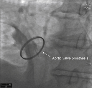
FIGURE 3-30 Prosthetic aortic valve. A bileaflet valve is noted in the aortic position in this radiograph obtained in the LAO projection. In the still frame, the leaflets are captured in the open position. Note that this valve is smaller than the valve that was previously visualized in the mitral position.
FIGURE 3-31 Dialated cardiomyopathy. Diastole (A) and systole (B). A pigtail catheter is placed in the left ventricle. This catheter is not in the ideal position because it is located near the mitral valve apparatus. This image, obtained in the RAO projection, allows visualization of the anterolateral (long arrow), apical (arrowhead), and diaphragmatic (short arrow) segments of myocardium. As contrast medium is injected into the ventricle, the movement of the myocardial segments is determined by the reduction of the ventricular cavity size, allowing estimation of left ventricular systolic function. Each individual segment is also evaluated for contractility and described accordingly. Hypokinesis is defined as reduced inward motion during systole. Akinesis is the absence of inward motion during systole. Dyskinesis is defined as paradoxical outward motion during systole. The LV in this image is dilated; overall contractility is moderately impaired. The ejection fraction is estimated at approximately 30%.
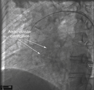
FIGURE 3-32 Aortic valve calcification with severe aortic insufficiency. A pigtail catheter has been advanced into the ascending aorta from the femoral approach. Before injection of contrast medium, a radiolucent area is noted at the location of the aortic valve, representing heavy calcification of the aortic valve apparatus. As contrast is injected, the LV quickly becomes filled at the same density of the aorta, demonstrating severe aortic insufficiency. In addition, the aortic root is mildly dilated.
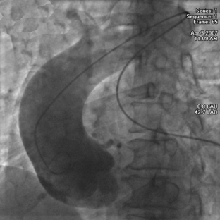
FIGURE 3-33 Dilated aortic root. In this image, a pigtail catheter has been advanced into the ascending aorta via the femoral approach. The course of the catheter appears unusual as it comes up to and crosses the aortic arch secondary to severe tortuosity of the aorta. After contrast injection, the aortic root and ascending aorta are noted to be quite enlarged. Compare the size of aortic root to the size of the aortic arch after the innominate artery.
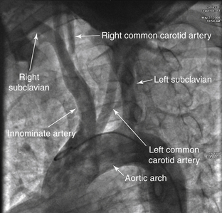
FIGURE 3-34 Bovine aortic arch. A pigtail catheter has been advanced into the ascending aorta via the femoral approach, and this image has been obtained in the AP projection. The normal orientation of the great vessels includes three separate ostia: the right innominate, then the left common carotid, and finally the left subclavian arteries. In this patient, the origin of the right innominate artery is located in the proper location; however, the origin of the left carotid artery is from a shared common trunk with the right innominate artery, termed a bovine arch. This orientation occurs in 15% of patients. A less common finding is to have the left common carotid artery originate from the innominate artery proper, which occurs in approximately 10% of patients.
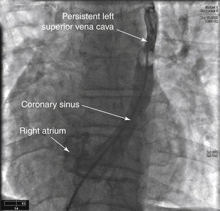
FIGURE 3-35 Persistent superior vena cava. A balloon-tipped catheter has been advanced through the cardiac silhouette. The catheter has passed through the IVC into the right atrium through the coronary sinus into a persistent left SVC. Persistent left SVC is the most common abnormality of the thoracic venous system, present in 0.3% of the population. It is often associated with other cardiac abnormalities, such as VSD and ASD.
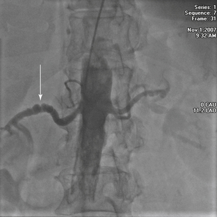
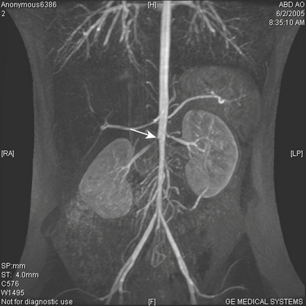
FIGURE 3-36 Fibromuscular dysplasia. Image of the abdominal aorta obtained in the AP projection. A pigtail catheter has been advanced from the radial artery to the level of the renal arteries. The right renal artery appears to have a “string-of-beads” appearance (arrow), which suggests fibromuscular dysplasia (not optimally imaged here). This autosomal dominant disorder, usually discovered between the ages of 14 and 50 years, is characterized by fibrous thickening of any of the layers of the arterial wall. Most commonly the medial layer is affected and causes narrowing of the arterial lumen. If intervention is needed in these cases, angioplasty is most often done without the need for stenting.
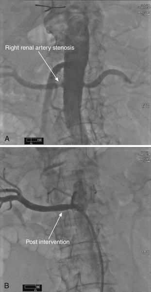
FIGURE 3-37 Bilateral renal artery stenosis and right renal artery stent placement. A, A 78-year-old female with resistant hypertension presented for evaluation. On examination, an abdominal bruit was auscultated. Noninvasive imaging diagnosed bilateral renal artery stenosis. Therefore, the patient underwent renal angiography. Using a pigtail catheter, via the right femoral artery, an abdominal aortic angiogram was performed. This confirmed bilateral renal artery stenosis, right more severe than the left. B, The patient underwent stent placement to the right renal artery with successful reduction of the lesion.
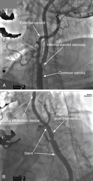
FIGURE 3-38 Left internal carotid artery stenosis and stent placement with residual stenosis. A, A 71-year-old female presented with amaurosis fugax of the left eye. Noninvasive evaluation was consistent with significant left carotid stenosis. At angiography, a lesion was noted in the proximal segment of the left internal carotid artery. B, Angiogram obtained after intervention. A tapered stent has been deployed into the left distal common carotid artery crossing into the proximal internal carotid artery. Note that there is residual stenosis present, and the ostium of the external carotid artery is now much narrower compared to the pre-intervention angiogram.
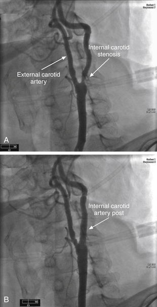
FIGURE 3-39 Left internal carotid artery stenosis and stent placement. A, A 75-year-old female presented for evaluation several weeks after an episode of transient slurring of her speech. Noninvasive imaging was consistent with severe left internal carotid artery stenosis. This angiogram of the left carotid artery was obtained in the LAO projection. This orientation separates the origins of the internal and external carotid arteries. A significant stenosis at the origin of the left internal carotid artery is apparent. B, A tapered stent was deployed across the lesion. Final angiograms show no evidence of residual stenosis.
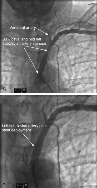
FIGURE 3-40 Left subclavian stenosis and stent placement. A, An 80-year-old female presented with complaints of weakness, dizziness, and left arm discomfort with use of that arm. Examination suggested left subclavian stenosis. An angiogram was obtained using a Judkins right catheter placed at the origin of the left subclavian artery. Note the stenoses at the ostium and mid segment of the left subclavian artery. The vertebral artery is also visualized. On motion angiography, biphasic flow was present within the vertebral artery indicating that the lesions were significant and compromising flow to the arm. B, This image was obtained after a stent was successfully placed across both lesions within the left subclavian artery. In addition, it was noted on motion angiography that a normal flow pattern was restored within the vertebral artery.
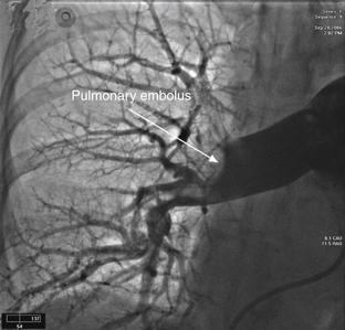
FIGURE 3-41 Right pulmonary artery embolus. A selective right pulmonary artery angiogram is shown here. Note the large filling defect present in the distal portion of the artery. This is a large pulmonary embolus. Pulmonary angiography remains the gold standard for diagnosis of pulmonary emboli. Nowadays, however, it is rarely performed. More commonly, a CT scan of the chest with contrast or a V/Q scan is obtained in a patient with symptoms suggestive of pulmonary embolus.
Cardiovascular Imaging Review Expert Consult
WhatsApp us