Analyzers
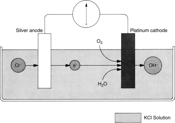
A Analyzers operating on the polarographic principle (Clark electrode) (Figures 37-1 and 37-2)
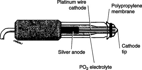
1. The basic overall chemical reaction occurring in electrode system is
2. The analyzer is composed of two electrodes immersed in a potassium chloride electrolyte solution.
a. At the silver anode, oxidation of chloride ion to silver chloride takes place. This reaction releases electrons, developing a current.
b. At the platinum cathode, oxygen is reduced to form OH− ions, thus consuming electrons produced from the anode.
3. In solution the greater the partial pressure of oxygen, the greater the current produced and used.
4. A −0.6 volt (V) polarizing voltage is applied to the anode.
5. This voltage is needed to maintain direction of current from anode to cathode through the electrolyte solution.
6. At −0.6 V oxygen is the only respiratory gas that will be readily reduced.
7. The tip of the Clark electrode is covered with a polypropylene membrane that allows slow diffusion of oxygen from blood or gas being analyzed.
8. This analyzer type directly measures partial pressure of the gas. For this reason the analyzer must be carefully calibrated at varying altitudes and to changing atmospheric pressures.
9. The analyzer is used in all respiratory gas mixtures and is the type incorporated into most blood gas analyzer systems.
10. Measurement of flow of electrons is referred to as an amperometric measurement.
11. Response times for Clark electrode oxygen analyzers range between 10 and 30 seconds.
B Analyzers operating using a galvanic cell
1. The galvanic cell is similar to a battery cell that uses oxygen to create a current between its electrodes.
2. Current is continually produced if the cell is exposed to oxygen; thus the life of the cell depends on duration and frequency of use.
3. The analyzer is composed of two electrodes immersed in an alkali metal hydroxide solution. Generally the electrolyte is potassium hydroxide, but some models use cesium hydroxide.
a. A lead anode, in the presence of oxygen, produces a current as a result of an oxidation reaction with the hydroxide compound.
b. A gold cathode, in the presence of oxygen, produces the following reaction.
c. The overall reactions for galvanic cell and polarographic analyzers are the same.
4. The current is measured from anode to cathode, which allows completion of an electric circuit.
5. The greater the partial pressure of oxygen, the greater the measured current.
6. As with the polarographic analyzer the galvanic cell measures the partial pressure of oxygen and consequently must be carefully calibrated at varying altitudes and atmospheric pressure.
7. The response time for galvanic cell analyzers is longer, sometimes taking as long as 60 seconds.
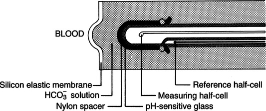
II pH (Sanz) Electrode (Figures 37-3 and 37-4)
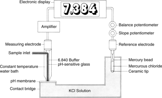
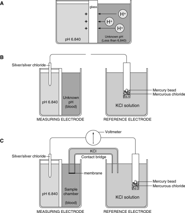
A The electrode is composed of two half-cells connected via a potassium chloride electrolyte bridge.
B The measuring half-cell has two chambers separated by pH-sensitive glass, which allows measurement of voltage differences across the glass.
1. The enclosed buffer chamber with a buffer of a constant pH surrounds the pH-sensitive glass capillary tube.
2. The sample chamber capillary tube allows blood to be in contact with the pH-sensitive glass.
C The reference half-cell is immersed in potassium chloride solution, which allows completion of the basic electrical circuit while providing constant reference voltage.
D As a result of electric activity on the pH-sensitive glass, a potential difference can be measured.
E The potential difference is measured on a voltmeter calibrated in pH units.
F This type of system comparing voltage measurements is termed potentiometer.
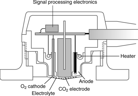
III Pco2 (Severinghaus) Electrode (Figure 37-5)
A The Pco2 electrode is a modified pH electrode.
B The Pco2 is measured indirectly by determining the change in pH of an NaHCO3 solution.
C The electrode is composed of two half-cells, each composed of silver/silver chloride.
1. Carbon dioxide diffuses across a silicon membrane into an NaHCO3 electrolyte solution.
2. After the solution is entered carbon dioxide reacts with water to form hydrogen and bicarbonate ions:
3. The H+ formed sets up a potential difference across the pH-sensitive glass in the measuring half-cell.
E All other aspects of the electrode are consistent with the pH electrode.
F The potential difference is measured on a voltmeter and reflected as millimeters of mercury of carbon dioxide. (Note: The Po2 (Clark) electrode for blood gas analyzers is covered in Section I, A.)
A Bedside arterial blood gas (ABG) analysis (Figure 37-6)
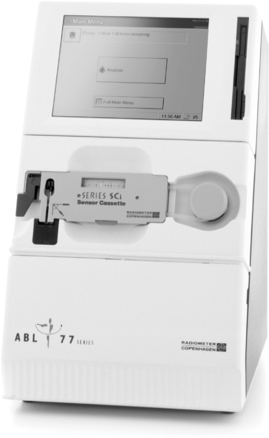
1. Bedside ABG analysis can be cost effective.
2. Some models can measure several additional chemistry and hematology parameters, including
B Some are portable roll-about or handheld and operate via alternating current (AC) or direct current (DC).
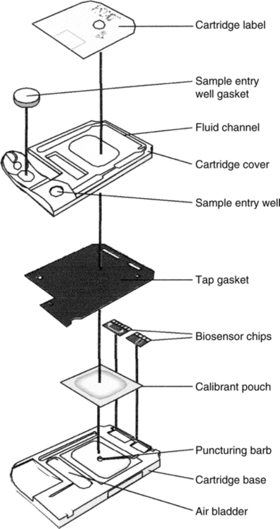
C Analysis of blood takes place in a disposable, self-calibrating cartridge (Figure 37-7).
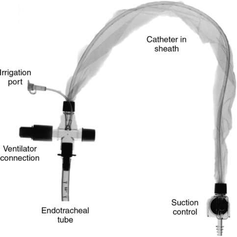
V Indwelling (Intraarterial) Continuous Blood Gas Monitoring (Figure 37-8)
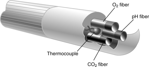
A Current technology using fiberoptic photochemical sensors or optodes
VI Transcutaneous Po2 (TcPo2) and Pco2 (TcPco2) Monitoring
A Both of these techniques make use of miniaturized blood gas (Clark and Severinghaus) electrodes (Figure 37-9).
a. Oxygen molecules diffusing through the skin diffuse through the semipermeable membrane covering the Clark electrode.
b. The skin surface under the electrode is heated to approximately 42° C to facilitate diffusion and to arterialize the blood.
c. Normally electrodes are placed on flat surfaces of the chest and abdomen.
d. This electrode is reasonably accurate if perfusion is normal and the skin over which it is placed is thin.
a. The skin under the electrode is heated to approximately 44° C.
b. Heating of the skin increases diffusion, allowing more carbon dioxide to diffuse, but may increase local metabolism and carbon dioxide production.
c. Electrodes are placed on the chest and abdomen.
d. As long as perfusion is adequate and diffusion is normal, TcPco2 accurately tracks Pco2.
e. TcPo2 and TcPco2 electrodes should be changed every 2 to 6 hours to prevent thermal injury.
VII Spectrophotometric Analyzers: Oximetry
A A spectrophotometer is an apparatus that determines the light absorbance of matter in solution by the quantity of light absorbed in passing through the fluid.
1. Molecules of a substance in solution can absorb light waves. Various substances absorb differing spectra.
2. Spectrophotometers create light waves specific to the substance to be measured.
3. Light waves of specific spectra are passed through a sample and measured.
4. Because the amount of input light waves is constant, measuring the output waves allows determination of the amount of light absorption by the sample.
5. Finally, according to the Lambert-Beer law, the absorption of light by a solution is a function of the concentration of the solute and the absorption depth of the solution. The greater the sample absorption, the greater the concentration of the substance measured because the absorption depth is a constant determined by the sample chamber.
B Functional components of spectrophotometers
1. Light source of known intensity
2. Sample chamber of known depth
C Types of spectrophotometers commonly used
1. Pulse oximeters (Figure 37-10)
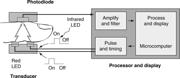
a. These units use two wavelengths of light: red and infrared.
b. The absorption of light by oxyhemoglobin and reduced hemoglobin is compared.
c. Both require a pulsating arterial bed for operation. Typical measurement sites are
d. The emitter and detector are placed on each side of the capillary bed.
e. Most units fail to function if a pulse is not noticeable.
f. These units measure oxyhemoglobin saturation with an accuracy of ±2% to ±5% within the 80% to 100% saturation range.
g. They are frequently used on all sizes of patients in all clinical settings to monitor oxyhemoglobin saturation.
3. Capnography (end-tidal CO2 monitoring) (Figure 37-11)
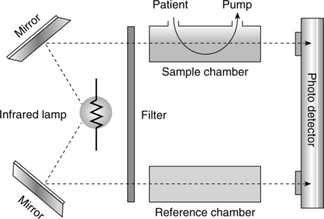
a. Infrared capnometer is the most common technology used.
b. This device uses the radio absorptive quality of CO2.
c. Filtered infrared light source passes through a sample chamber.
d. A lens focuses the remaining unabsorbed radiation onto a photo detector.
e. The greater the concentration of CO2, the less infrared light will arrive at the photo detector, which alters the electrical output signal.
f. There are advantages and disadvantages to using a mainstream sampling and a side-stream sampling method.
g. End-tidal CO2 readings also are altered by any factor affecting deadspace.
h. The greater the deadspace, the poorer the correlation of end-tidal CO2 with Paco2.
(1) A normal capnogram tracing is depicted in Figure 37-12.
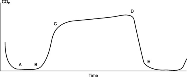
(2) From point a to b, gas is exhaled from the anatomic deadspace; no CO2 is present.
(3) From point b to c, there is a changeover from deadspace to alveolar gas, and the amount of exhaled CO2 rapidly increases.
(4) From point c to d, gas is exhaled entirely from alveoli. In this stage a gently sloping plateau should be established.
(5) From point d to e, inspiration begins, which continues into point a.
i. Many variations in the normal capnogram are noticed clinically (Figure 37-13).
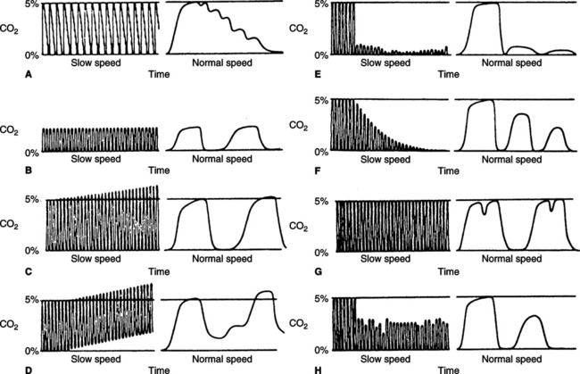
(1) Pulsing of exhaled gas caused by cardiac oscillations is noted in Figure 37-13, A.
(2) Hyperventilation is noted in Figure 37-13, B. The percentage of exhaled CO2 is normally decreased.
(3) The beginning of hypoventilation is noted in Figure 37-13, C. Carbon dioxide levels start to increase.
(4) Rebreathing of CO2 results in the baseline CO2 level increasing above zero (see Figure 37-13, D).
(5) A disconnected mechanical ventilator or apnea in spontaneous ventilation is indicated by a sudden loss of the capnogram tracing (see Figure 37-13, E).
(6) A rapid progressive decay in the plateau is noted during cardiac arrest or severely developing hypotension. Because of loss of perfusion, deadspace markedly increases and CO2 decreases (see Figure 37-13, F).
(7) Spasmodic contraction of the diaphragm or the interruption of exhalation by an incomplete breath is illustrated in Figure 37-13, G.
(8) A periodic decrease in CO2 level and a loss of plateau are associated with same ineffective tidal breaths or poor sampling (see Figure 37-13, H).
VIII Nitric Oxide and Nitrogen Dioxide Analyzers (Figures 37-14 and 37-15)
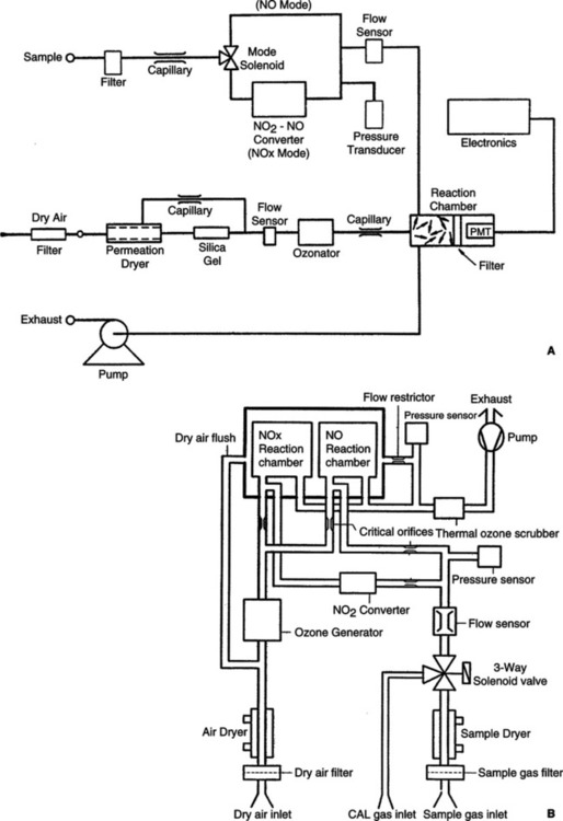
A Nitric oxide and nitrogen dioxide analyzers
a. Chemiluminescence monitoring
(1) Available in single- or dual-reaction chambers
(2) Measures gas concentration by stimulated photoemission
(3) Sample gas reacts with ozone (O3) to produce NO2 (nitrogen dioxide).
(6) The NO2* releases a photon NO2* → + (photon).
(7) Measured by a photomultiplier tube that proportionately converts the intensity of the luminescence into an electrical signal for display.
(8) NO2 is measured indirectly by converting NO2 to NO and measures total NO concentrations in either a thermal catalytic converter (600 to 800° C) or chemical converter (using molybdenum or carbon).
(9) 2 NO2 → 2 NO + O2 (thermal catalytic converter)
(10) 3 NO2 + Mo → MoO3 + 3 NO (chemical converter)
(11) NO2 concentration is the difference between total nitrogen oxides measured (NOx) and the NO concentration.
(12) Advantages: Chemical converters are more stable.
(13) Disadvantages: Chemical must be replenished.
(14) Oxygen concentrations near 100% decrease the NO reading between 7% and 15% and the NOx by between 15% and 26%.
(1) Based on the principle these gases react with an electrolyte solution
(2) Electrons are liberated and generate a current between two polarized electrodes.
(3) Reactions occurring to measure NO
(4) Reactions occurring to measure NO2
(5) Accuracy can be affected by direct pressure from mechanical ventilators but can be minimized by using a side-stream sampling technique.