Anaesthetic Apparatus
It is essential that anaesthetists check that all equipment is functioning correctly before they proceed to anaesthetize a patient (see Ch 21). In some respects, the routine of testing anaesthetic equipment resembles the airline pilot’s checklist, which is an essential preliminary to aircraft flight.
It is convenient to describe anaesthetic apparatus sequentially from the supply of gases to point of delivery to the patient. This sequence is shown in Table 15.1.
TABLE 15.1
Classification of Anaesthetic Equipment Described in this Chapter
Supply of gases:
From outside the operating theatre
From cylinders within the operating theatre, together with the connections involved
The anaesthetic machine:
Unions
Cylinders
Reducing valves
Flowmeters
Vaporizers
Safety features of the anaesthetic machine
Anaesthetic breathing systems
Ventilators
Apparatus used in scavenging waste anaesthetic gases
Apparatus used in interfacing the patient to the anaesthetic breathing system:
Laryngoscopes
Tracheal tubes
Catheter mounts and connectors
Accessory apparatus for the airway:
Anaesthetic masks and airways
Forceps
Laryngeal sprays
Bougies
Mouth gags
Stilettes
Suction apparatus
GAS SUPPLIES
Bulk Supply of Anaesthetic Gases


Bulk Store
Oxygen Concentrators: Recently, oxygen concentrators have been used to supply hospitals and it is likely that the use of these devices will increase in future. The oxygen concentrator depends upon the ability of an artificial zeolite to entrap molecules of nitrogen. These devices cannot produce pure oxygen, but the concentration usually exceeds 90%; the remainder comprises nitrogen, argon and other inert gases. Small oxygen concentrators are provided for domiciliary use.
Terminal Outlets


Gas Supplies
Gas supplies to the anaesthetic machine should be checked at the beginning of each session to ensure that the gas which issues from the pipeline or cylinder is the same as that which passes through the appropriate flowmeter. This ensures that pipelines are not connected incorrectly. Both the machine in the operating theatre and that in the anaesthetic room should be checked. Checking of anaesthetic machine and medical gas supplies is discussed fully in Chapter 20 (‘The operating theatre environment’).
CYLINDERS
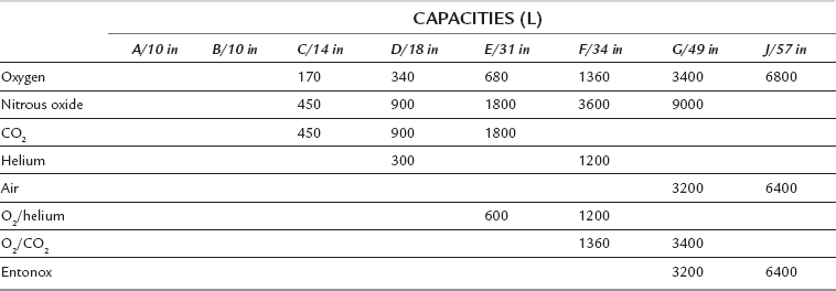
The colour codes used for medical gas cylinders in the United Kingdom are shown in Table 15.2. Different colours are used for some gases in other countries. There is a proposal to harmonize cylinder colours throughout Europe. The body will be painted white and only the shoulders will be colour-coded. The shoulder colours for medical gases will correspond to the current UK colours but will be horizontal rings rather than quarters. Cylinder sizes and capacities are shown in Table 15.3.
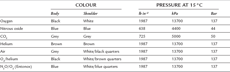
Nitrous oxide and carbon dioxide cylinders contain liquid and vapour and the cylinders are filled to a known filling ratio (see Ch 14). The cylinder pressure cannot be used to estimate its contents because the pressure remains relatively constant until after all the liquid has evaporated and the cylinder is almost empty, though cylinder pressure may change slightly due to temperature changes during use. The contents of nitrous oxide and carbon dioxide cylinders can be estimated from the weight of the cylinder.
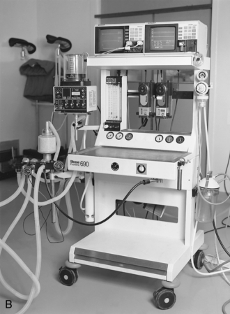
THE ANAESTHETIC MACHINE
The anaesthetic machine comprises:
 a means of supplying gases either from attached cylinders or from piped medical supplies via appropriate unions on the machine
 methods of measuring flow rate of gases
 apparatus for vaporizing volatile anaesthetic agents
 breathing systems and a ventilator for delivery of gases and vapours from the machine to the patient
 apparatus for scavenging anaesthetic gases in order to minimize environmental pollution.
Pressure Regulators
Pressure regulators are used on anaesthetic machines for three purposes:
 to reduce the high pressure of gas in a cylinder to a safe working level
 to prevent damage to equipment on the anaesthetic machine, e.g. flow control valves

The principles underlying the operation of pressure regulators are described in detail in Chapter 14.
Flow Restrictors
A different type of flow restrictor may be fitted also to the downstream end of the vaporizers to prevent back-pressure effects (see Ch 14). The absence of such a flow restrictor may be detected if a gas-driven ventilator such as the Manley is used, as this leads to fluctuations in the positions of the flowmeter bobbins during the respiratory cycle.
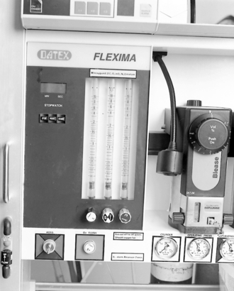
Flowmeters
The principles of flowmeters are described in detail in Chapters 14 and 16.
Problems with Flowmeters
 Non-vertical tube. This causes a change in shape of the annulus and therefore variation in flow. If the bobbin touches the side of the tube, resulting friction causes an even more inaccurate reading.


 Leakage. This results usually from defects in the top sealing washer of a flowmeter.
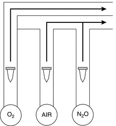
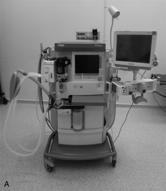
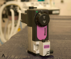
It is unfortunate that, in the UK, the standard position of the oxygen flowmeters is on the left followed by either nitrous oxide or air (if all three gases are supplied). On several recorded occasions, patients have suffered damage from hypoxia because of leakage from a broken flowmeter tube in this type of arrangement, as oxygen, being at the upstream end, passes out to the atmosphere through any leak. This problem is reduced if the oxygen flowmeter is placed downstream (i.e. on the right-hand side of the bank of flowmeters) as is standard practice in the USA. In the UK, this problem is now avoided by designing the outlet from the oxygen flowmeter to enter the back bar downstream from the outlets of other flowmeters (Fig. 15.1). Most modern anaesthetic machines do not have a flowmeter for carbon dioxide. Some new anaesthetic machines such as Primus Dräger (Fig 15.2A) do not have traditional flowmeters; gas delivery is under electronic control and there is an integrated heater within a leak-tight breathing system. The gas flow is indicated electronically by a numerical display. In the event of an electrical failure, there is a pneumatic back-up which continues the delivery of fresh gas. These machines are particularly well suited to low and minimal flow anaesthesia and they use standard vaporizers.
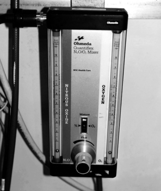
Quantiflex
The Quantiflex mixer flowmeter (Fig. 15.3) eliminates the possibility of reducing the oxygen supply inadvertently. One dial is set to the desired percentage of oxygen and the total flow rate is adjusted independently. The oxygen passes through a flowmeter to provide evidence of correct functioning of the linked valves. Both gases arrive via linked pressure-reducing regulators. The Quantiflex is useful in particular for varying the volume of fresh gas flow (FGF) from moment to moment whilst keeping the proportions constant. In addition, the oxygen flowmeter is situated downstream of the nitrous oxide flowmeter.
Vaporizers
The principles of vaporizers are described in detail in Chapter 14.
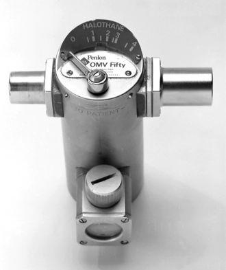
Modern vaporizers may be classified as:
 Drawover vaporizers. These have a very low resistance to gas flow and may be used for emergency use in the field (e.g. Oxford miniature vaporizer; OMV) (Fig 15.5).
 Plenum vaporizers. These are intended for unidirectional gas flow, have a relatively high resistance to flow and are unsuitable for use either as drawover vaporizers or in a circle system. Examples include the ‘TEC’ type in which there is a variable bypass flow. Commonly used plenum vaporizers are shown in Figures 15.6 and 15.7A.
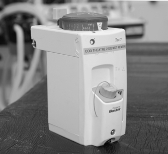
Temperature regulation in the TEC vaporizers is achieved using a bimetallic strip.
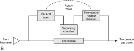
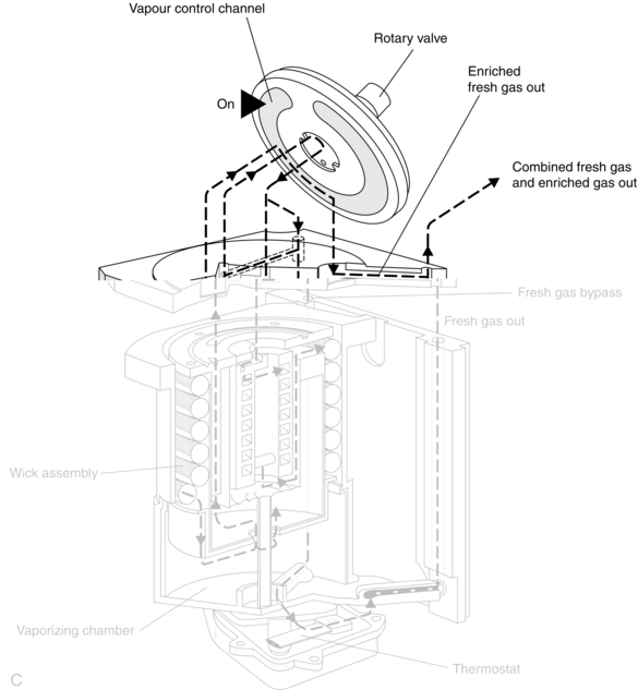
There has been more than one model of the ‘TEC’ type of vaporizer. The TEC Mark 2 vaporizer is now obsolete. The TEC Mark 3 had characteristics which were an improvement on the Mark 2. These included improved vaporization as a result of increased area of the wicks, reduced pumping effect by having a long tube through which the vaporized gas leaves the vaporizing chamber, improved accuracy at low gas flows and a bimetallic strip which is situated in the bypass channel and not the vaporizing chamber. In the Mark 4, the improvements were as follows: no spillage into the bypass channel if the vaporizer was accidentally inverted, and the inability to turn two vaporizers on at the same time when on the back bar of the anaesthetic machine. The TEC Mark 5 vaporizer (Fig. 15.7A–C) has improved surface area for vaporization in the chamber, improved key-filling action and an easier mechanism for switching on the rotary valve and lock with one hand. Desflurane presents a particular challenge because it has a saturated vapour pressure of 664 mmHg (89 kPa) at 20 °C and a boiling point of 23.5 °C. In order to combat this problem, a new vaporizer, the TEC 6, was developed (Fig. 15.8). It is heated electrically to 39 °C with a pressure of 1550 mmHg (approx. 2 bar). The vaporizer has electronic monitors of vaporizer function and alarms. The FGF does not enter the vaporization chamber. Instead, desflurane vapour enters into the path of the FGF. A percentage control dial regulates the flow of desflurane vapour into the FGF. The dial calibration is from 1% to 18%. The vaporizer has a back-up 9 volt battery in case of mains failure. The functioning of the vaporizer is shown diagrammatically in Figure 15.9.
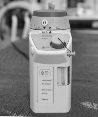
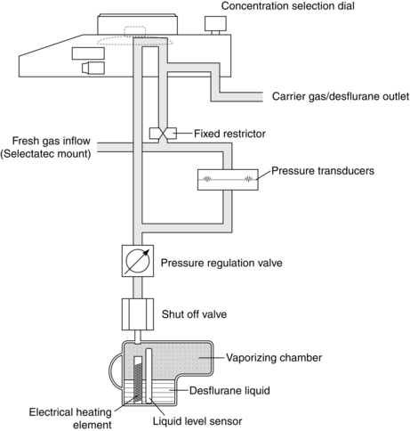
FIGURE 15.9 The TEC 6 desflurane vaporizer. Liquid in the vaporizing chamber is heated and mixed with fresh gas; the pressure-regulating valve balances both fresh gas pressure and anaesthetic vapour pressure.
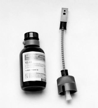
Anaesthetic-specific connections are available to link the supply bottle (container of liquid anaesthetic agent) to the appropriate vaporizer (Fig. 15.10). These connections reduce the extent of spillage (and thus atmospheric pollution) and also the likelihood of filling the vaporizer with an inappropriate liquid. In addition to being designed specifically for each liquid, the connections themselves may be colour-coded (e.g. purple for isoflurane, yellow for sevoflurane, orange for enflurane, red for halothane).
SAFETY FEATURES OF MODERN ANAESTHETIC MACHINES
 Specificity of probes on flexible hoses between terminal outlets and connections with the anaesthetic machine. The flexible hoses are colour-coded and have non-interchangeable screw-threaded connectors to the anaesthetic machine.

 Pressure relief valves on the downstream side of pressure regulators.
 Flow restrictors on the upstream side of flowmeters.
 Arrangement of the bank of flowmeters such that the oxygen flowmeter is on the right (i.e. downstream side) or oxygen is the last gas to be added to the gas mixture being delivered to the back bar (Fig. 15.1).

 Pressure gauges indicate the pressures in the pipelines and the cylinders.

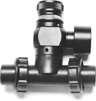
 Mounting of vaporizers on the back bar. There is concern about contamination of vaporizers if two vaporizers are turned on at the same time. Temperature-compensated vaporizers contain wicks and these can absorb a considerable amount of anaesthetic agent. If two vaporizers are mounted in series, the downstream vaporizer could become contaminated to a dangerous degree with the agent from the upstream vaporizer. However, the newer TEC Mark 4 and 5 vaporizers have the interlocking Selectatec system (Fig. 15.11) which has locking rods to prevent more than one vaporizer being used at the same time. When a vaporizer is mounted on the back bar, the locking lever needs to be engaged (Mark 4 and 5). If this is not done, the control dial cannot be moved.
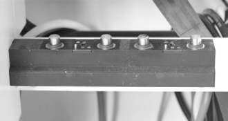
FIGURE 15.11 A Selectatec block on the back bar of an anaesthetic machine. This permits the vaporizer to be changed rapidly without interrupting the flow of carrier gas to the patient.


 activation depends on the pressure of oxygen itself and does not depend on the pressure of any other gas
 does not use a battery or mains power
 gives a signal which is audible, of sufficient duration and of distinctive character
 should give a warning of impending failure and a further warning that failure has occurred
 should interrupt the flow of all other gases when it comes into operation.


BREATHING SYSTEMS
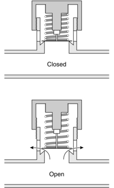
Adjustable Pressure-Limiting Valve
Several valves of this type are available. They comprise a lightweight disc (Fig. 15.12) which rests on a ‘knife edge’ seating to minimize the area of contact and reduce the risk of adhesion resulting from surface tension of condensed water. The disc has a stem which acts as a guide to position it correctly. A light spring is incorporated in the valve so that the pressure required to open it may be adjusted. During spontaneous breathing, the tension of the spring is low so that the resistance to expiration is minimized. During controlled ventilation, the valve top is screwed down to increase the tension in the spring so that gas leaves the system at a higher pressure than during spontaneous ventilation. Modern valves, even when screwed down fully, open at a pressure of 60 cm H2O. Most valves are encased in a hood for scavenging.
Classification of Breathing Systems
In 1954, Mapleson classified anaesthetic breathing systems into five types (Fig. 15.13); the Mapleson E system was modified subsequently by Rees, but is classified as the Mapleson F system. The systems differ considerably in their ‘efficiency’, which is measured in terms of the fresh gas flow (FGF) rate required to prevent rebreathing of alveolar gas during ventilation.
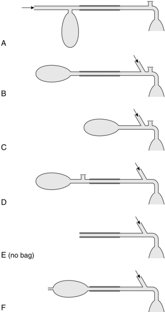
FIGURE 15.13 Mapleson classification of anaesthetic breathing systems. The arrow indicates entry of fresh gas to the system.
Mapleson A Systems
During spontaneous ventilation (Fig. 15.14), there are three phases in the ventilatory cycle: inspiratory, expiratory and the expiratory pause. Gas is inhaled from the system during inspiration (Fig. 15.14B). During the initial part of expiration, the reservoir bag is not full and thus the pressure in the system does not increase; exhaled gas (the initial portion of which is dead space gas) passes along the corrugated tubing towards the bag (Fig. 15.14C), which is filled also by fresh gas from the anaesthetic machine. During the latter part of expiration, the bag becomes full; the pressure in the system increases and the spill valve opens, venting all subsequent exhaled gas to atmosphere. During the expiratory pause, continued flow of fresh gas from the machine pushes exhaled gas distally along the corrugated tube to be vented through the spill valve (Fig. 15.14D). Provided that the FGF rate is sufficiently high to vent all alveolar gas before the next inspiration, no rebreathing takes place from the corrugated tube. If the system is functioning correctly and no leaks are present, an FGF rate equal to the patient’s alveolar minute ventilation is sufficient to prevent rebreathing. In practice, a higher FGF is selected in order to compensate for leaks; the rate selected is usually equal to the patient’s total minute volume (approximately 6 L min–1 for a 70-kg adult).
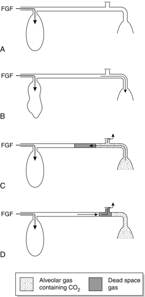
FIGURE 15.14 Mode of action of Magill attachment during spontaneous ventilation. See text for details. FGF, fresh gas flow.
The characteristics of the Mapleson A system are different during controlled ventilation (Fig. 15.15). At the end of inspiration (produced by the anaesthetist squeezing the reservoir bag), the bag is usually less than half full (see below). During expiration, dead space and alveolar gas pass along the corrugated tube and are likely to reach the reservoir bag, which therefore contains some carbon dioxide (Fig. 15.15A). During inspiration, the valve does not open initially because its opening pressure has been increased by the anaesthetist in order to generate a sufficient pressure within the system to inflate the lungs. Thus, alveolar gas re-enters the patient’s lungs and is followed by a mixture of fresh, dead space and alveolar gases (Fig. 15.15B). When the valve does open, it is this mixture which is vented (Fig. 15.15C). Consequently, the FGF rate must be very high (at least three times alveolar minute volume) to prevent rebreathing. The volume of gas squeezed from the reservoir bag must be sufficient both to inflate the lungs and to vent gas from the system.
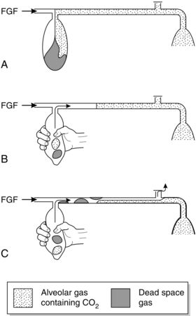
FIGURE 15.15 Mode of action of Magill attachment during controlled ventilation. See text for details. FGF, fresh gas flow.
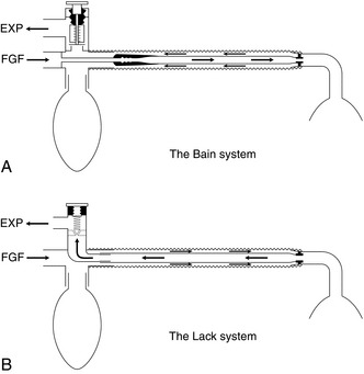
The major disadvantage of the Magill attachment during surgery is that the spill valve is attached close to the mask. This makes the system heavy, particularly when a scavenging system is used, and it is inconvenient if the valve is in this position during surgery of the head or neck. The Lack system (Fig. 15.16B) is a modification of the Mapleson A system with a coaxial arrangement of tubing. This permits positioning of the spill valve at the proximal end of the system. The inner tube must be of sufficiently wide bore to allow the patient to exhale with minimal resistance. The Lack system is not quite as efficient as the Magill attachment.
Mapleson D System
The Mapleson D arrangement is inefficient during spontaneous breathing (Fig. 15.17). During expiration, exhaled gas and fresh gas mix in the corrugated tube and travel towards the reservoir bag (Fig. 15.17B). When the reservoir bag is full, the pressure in the system increases, the spill valve opens and a mixture of fresh and exhaled gas is vented; this includes the dead space gas, which reaches the reservoir bag first (Fig. 15.17C). Although fresh gas pushes alveolar gas towards the valve during the expiratory pause, a mixture of alveolar and fresh gases is inhaled from the corrugated tube unless the FGF rate is at least twice as great as the patient’s minute volume (i.e. at least 12 L min–1 in the adult); in some patients, an FGF rate of 250 mL kg–1 min–1 is required to prevent rebreathing.
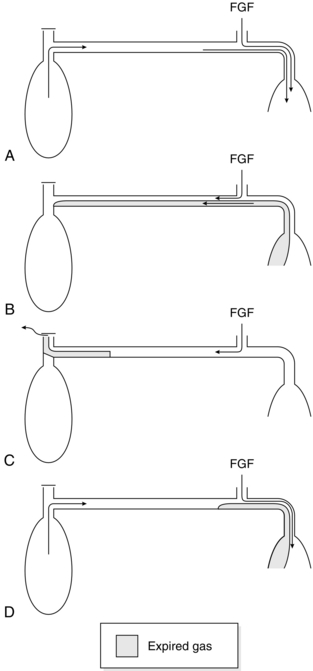
FIGURE 15.17 Mode of action of Mapleson D breathing system during spontaneous ventilation. See text for details. FGF, fresh gas flow.
However, the Mapleson D system is more efficient than the Mapleson A during controlled ventilation (Fig. 15.18), especially if an expiratory pause is incorporated into the ventilatory cycle. During expiration, the corrugated tubing and reservoir bag fill with a mixture of fresh and alveolar gas (Fig. 15.18A). Fresh gas fills the distal part of the corrugated tube during the expiratory pause (Fig. 15.18B). When the reservoir bag is squeezed, this fresh gas enters the lungs, and when the spill valve opens a mixture of fresh and alveolar gas is vented. The degree of rebreathing may thus be controlled by adjustment of the FGF rate, but this should always exceed the patient’s minute volume.
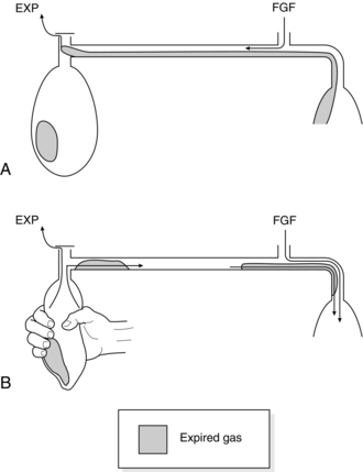
FIGURE 15.18 Mode of action of Mapleson D breathing system during controlled ventilation. See text for details. FGF, fresh gas flow.
The Bain coaxial system (Fig. 15.16A) is the most commonly used version of the Mapleson D system. FGF is supplied through a narrow inner tube. This tube may become disconnected, resulting in hypoxaemia and hypercapnia. Before use, the system should be tested by occluding the distal end of the inner tube transiently with a finger or the plunger of a 2-mL syringe; there should be a reduction in the flowmeter bobbin reading during occlusion and an audible release of pressure when occlusion is discontinued. Movement of the reservoir bag during anaesthesia does not necessarily indicate that fresh gas is being delivered to the patient.
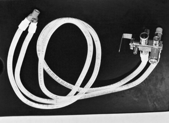
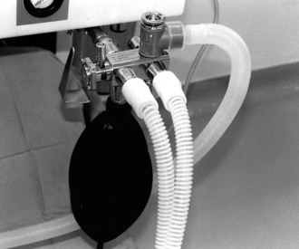
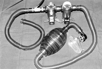
The Bain system may be used to ventilate the patient’s lungs with some types of automatic ventilator (e.g. Penlon Nuffield 200; Fig. 15.19). A 1-m length of corrugated tubing is interposed between the patient valve of the ventilator and the reservoir bag mount (Fig. 15.20); the spill valve must be closed completely. An appropriate tidal volume and ventilatory rate are selected on the ventilator and anaesthetic gases are supplied to the Bain system. During inspiration, the gas from the ventilator pushes a mixture of anaesthetic and alveolar gas from the corrugated outer tube into the patient’s lungs; during expiration, the ventilator gas and some of the alveolar gas are vented through the exhaust valve of the ventilator. The degree of rebreathing is regulated by the anaesthetic gas flow rate; a flow of 70–80 mL kg–1 min–1 should result in normocapnia and a flow of 100 mL kg–1 min–1 in moderate hypocapnia. A secure connection between the Bain system and the anaesthetic machine must be assured. If this connection is loose, a leak of fresh gas occurs; this causes rebreathing of ventilator gas and results in awareness, hypoxaemia and hypercapnia.
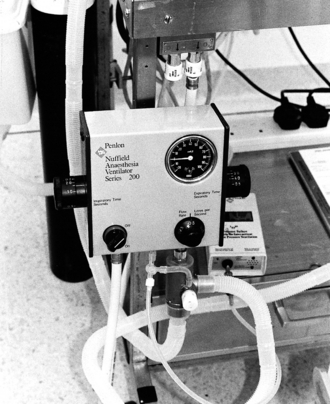
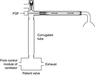
FIGURE 15.20 The Bain system for controlled ventilation by a mechanical ventilator (e.g. Penlon Nuffield 200). A 1-m length of corrugated tubing with a capacity of at least 500 mL is required to prevent gas from the ventilator reaching the patient’s lungs. PaCO2 is controlled by varying the fresh gas flow (FGF) rate.


Mapleson ADE System
It consists of two parallel lengths of 15-mm bore tubing; one delivers fresh gas and the other carries exhaled gas. One end of the tubing connects to the patient via a Y-connection and the other end contains the Humphrey block (Fig. 15.21). The Humphrey block (Fig. 15.22) consists of an APL valve, a lever to select spontaneous or controlled ventilation, a reservoir bag, a port to connect a ventilator and a safety pressure relief valve which opens at a pressure above 6 kPa.
Drawover Systems
Occasionally, it is necessary to administer anaesthesia at the scene of a major accident. If inhalation anaesthesia is required, it is necessary to use simple, portable equipment. The Triservice apparatus has been designed by the British armed forces for use in battle conditions (Fig. 15.23). It comprises a self-inflating bag, a non-rebreathing valve (e.g. Ambu E, Rubens) which vents all expired gases to atmosphere, one or two Oxford miniature vaporizers (which have a low internal resistance), an oxygen supply and a length of corrugated tubing which serves as an oxygen reservoir. Either spontaneous or controlled ventilation may be employed using this apparatus.
Rebreathing Systems
Soda Lime
Soda lime is the substance used most commonly for absorption of carbon dioxide in rebreathing systems. The composition of soda lime is shown in Table 15.4. The major constituent is calcium hydroxide, but sodium and potassium hydroxides may also be present. Absorption of carbon dioxide occurs by the following chemical reactions:
TABLE 15.4
| Ca(OH)2 | 94% |
| NaOH | 5% |
| KOH | < 1% or nil |
| Silica | 0.2% |
| Moisture content | 14–19% |


Water is required for efficient absorption. There is some water in soda lime and more is added from the patient’s expired gas and from the chemical reaction. The reaction generates heat and the temperature in the centre of a soda lime canister may exceed 60 °C. Sevoflurane has been shown to interact with soda lime to produce substances that are toxic in animals. However, this does not appear to impose any significant risk in humans (see Ch 2). There is new evidence suggesting that the presence of strong alkalis such as sodium and potassium hydroxides could be the trigger of the interaction between volatile agents and soda lime. New carbon dioxide absorbers are now being manufactured without these hydroxides in order to reduce this interaction.
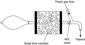
‘To-and-Fro’ (Waters’) System
This breathing system comprises a Mapleson C breathing system with a canister of soda lime interposed between the spill valve and the reservoir bag (Fig. 15.24). The soda lime granules nearest the patient become exhausted first, increasing the dead space of the system; in addition, the canister is positioned horizontally and gas may be channelled above the soda lime unless the canister is packed tightly. The system is cumbersome and there is a risk that patients may inhale soda lime dust from the canister.
Circle System
This system has replaced the ‘to-and-fro’ system. The soda lime canister is mounted on the anaesthetic machine, and inspiratory and expiratory corrugated tubing conducts gas to and from the patient (Fig. 15.25).The system incorporates a reservoir bag and spill valve and two low-resistance one-way valves to ensure unidirectional movement of gas (Fig. 15.26). These valves are normally mounted in glass domes so that they may be observed to be functioning correctly. The spill valve may be mounted close to the patient or beside the absorber; during surgery to the head or neck, it is more convenient to use a valve near the absorber. Fresh gas enters the system between the absorber and the inspiratory tubing.
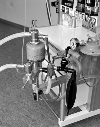
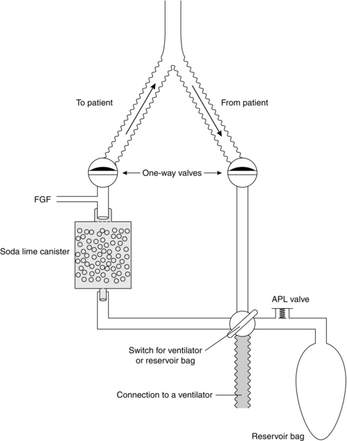
FIGURE 15.26 Mechanism of the circle system. The direction of gas flow is controlled via the unidirectional valves. A lever allows the ventilation to be either spontaneous through the reservoir bag and APL valve, or controlled by a ventilator.
Volatile anaesthetic agents may be delivered to a circle system in two ways:
 Vaporizer outside the circle (VOC) (Fig. 15.27A). If a standard vaporizer (e.g. TEC series) is used, it must be placed on the back bar of the anaesthetic machine because of its high internal resistance. If low FGF rates (< 1 L min–1) are used, the change in concentration of volatile anaesthetic agent achieved in the circle system is very small because of dilution, even if the vaporizer is set to deliver a high concentration (Fig. 15.28A). It may be necessary to change FGF rate rather than the vaporizer setting in order to achieve a rapid change in depth of anaesthesia. The concentration of volatile agent in the system depends on the patient’s expired concentration (which is recycled), the rate of uptake by the patient (which decreases with time and is lower with agents of low blood/gas solubility coefficient), the concentration of agent supplied and the FGF rate.
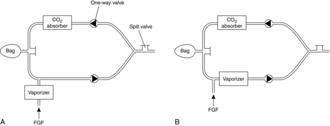
FIGURE 15.27 Diagrammatic representation of the circle system. (A) Vaporizer outside the circle (VOC). (B) Vaporizer inside the circle (VIC).
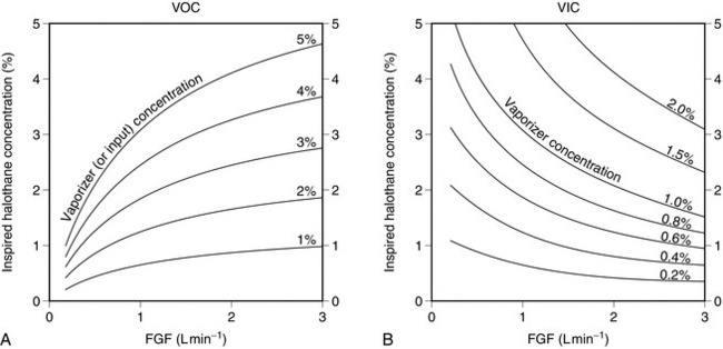
FIGURE 15.28 Variation of inspired concentration of halothane with fresh gas flow (FGF) rate. Total minute ventilation is 5 L min–1. (A) Vaporizer outside the circle (VOC); note that dilution of the fresh gas results in much lower concentrations in the circle system than the concentration set on the vaporizer unless FGF rate approaches 3 L min–1. (B) Vaporizer inside the circle (VIC); at low flow rates, lack of dilution of expired halothane concentration, with additional halothane vaporized during each inspiration, results in inspired concentrations much higher than those set on the vaporizer. Even at an FGF rate of 3 L min–1, inspired concentration is approximately 50% higher than the vaporizer setting.
 Vaporizer inside the circle (VIC) (Fig. 15.27B). Drawover vaporizers with a low internal resistance (e.g. Goldman) may be placed within the circle system. During each inspiration, vapour is added to the inspired gas mixture. In contrast to a VOC system, the inspired concentration is higher at low FGF rates because the expired concentration is diluted to a lesser extent (Fig. 15.28B) and the vaporizer adds to the concentration present in the expired gas. Very high concentrations of volatile agent may be inspired if minute volume is large; this risk is greatest if IPPV is employed.
If FGF rate is low, the use of the circle system by the inexperienced anaesthetist may result either in inadequate anaesthesia or in severe cardiovascular and respiratory depression. In addition, a hypoxic gas mixture may be delivered if low flow rates of a nitrous oxide/oxygen mixture are supplied, because after 10–15 min, oxygen is taken up in larger volumes than nitrous oxide. These difficulties can be overcome by monitoring the inspired concentrations of oxygen, carbon dioxide and volatile anaesthetic agent continuously (see Ch 16). The trainee anaesthetist must be aware that:
 It is inadvisable to use a VIC system unless inspired concentrations of anaesthetic agents are monitored continuously.


The advantages and disadvantages of the circle system are summarized in Table 15.5.
TABLE 15.5
Disadvantages and Advantages of the Circle System
| Disadvantages | Advantages |
| Cumbersome equipment | Inspired gases are humidified and warmed |
| Risk of delivering hypoxic mixture | Economical |
| Increased resistance to breathing | Minimal pollution |
| Slow change in the depth of anaesthesia | |
| Risk of awareness | |
| Risk of a rise in end-tidal CO2 | |
| Risk of unidirectional valves sticking | |
| Not ideal for paediatric patients breathing spontaneously | |
| Some inhalational agents may interact with soda lime |
Manual Resuscitation Breathing Systems


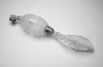
The self-inflating bag has a volume of approximately 1500 mL, 500 mL and 250 mL for the adult, child and infant sizes, respectively. The non-rebreathing valve has several components which ensure that, during the inspiratory phase, gas flows out of the bag into the patient and, during the expiratory phase, the valve ensures that exhaled gas escapes through the expiratory port without mixing with fresh gas. Three types of non-rebreathing systems are available, the Ruben, Ambu and Laerdal systems (Fig 15.29). Functionally, they are very similar but with some minor differences. The Ruben valve has a spring-loaded bobbin within the valve housing. The Ambu system has several series of valves which have either a single valve or double leaf valves to control unidirectional flow. The Laerdal system has three components: a duck-billed inspiratory/expiratory valve, a valve body housing inspiratory and expiratory ports and a non-return flap valve in the expiratory port.
VENTILATORS
Continuous clinical monitoring is essential when any ventilator is used, even those which incorporate sophisticated monitoring and warning devices. In addition to standard clinical monitoring systems attached to the patient (see Ch 16), the minimum acceptable monitoring of ventilator function includes measurement of expired tidal volume, airway pressure and inspired oxygen concentration; in addition, a ventilator disconnection alarm should be incorporated in the system. Continuous monitoring of end-tidal carbon dioxide, oxygen saturation and inspired anaesthetic gas concentrations is essential in the operating theatre.
The incorporation of a humidifier in the inspiratory limb, or of a condenser humidifier at the connection with the tracheal tube, is essential in long-term ventilation in the ICU. Bacterial filters (Fig. 15.30) are now recommended for all patients undergoing anaesthesia.
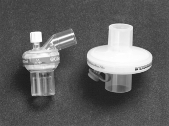
FIGURE 15.30 Bacterial filters and humidifiers which are used in breathing systems: left, a paediatric filter incorporated into an angle piece; right, an adult filter.
Inspiration
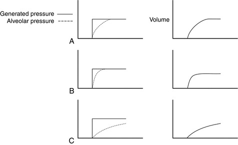
The pattern of volume change in the lung is determined by the characteristics of the ventilator. Ventilators may deliver a predetermined flow rate of gas (constant flow generators) or exert a predetermined pressure (constant pressure generators), although some machines produce a pattern which does not conform precisely to either category. Most flow generators produce a constant flow of gas during inspiration, although a few generate a sinusoidal flow pattern if the ventilator bellows is driven via a crank. The characteristics of constant flow and constant pressure generators are shown in Figure 15.31.
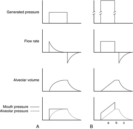
FIGURE 15.31 Graphs of generated pressure, mouth (or tracheal tube) and alveolar pressures, flow rate and alveolar volume changes during inspiration and subsequent expiration produced by a constant pressure generator (A) and a constant flow generator (B). A constant pressure generator exerts a low pressure (e.g. 1.5 kPa, 15 cmH2O). At the start of inspiration, the pressure in the alveoli is zero. Gas flows rapidly into the alveoli at a rate determined by airways resistance, resulting in rapid increases in alveolar volume and pressure. The mouth-alveolar pressure gradient decreases and flow rate, and consequently the rates of increase of alveolar volume and pressure, decrease also. When the alveolar pressure equals the ventilator pressure, flow ceases. A constant flow generator generates a very high internal pressure (e.g. 400 kPa) but has a high internal resistance to limit flow rate. The pressure gradient between machine and alveoli remains virtually constant throughout inspiration and thus flow rate is constant. The increases in alveolar volume and (assuming constant compliance) pressure are linear. Because flow rate is constant, the pressure gradient between mouth and alveoli is constant throughout inspiration. (a) Mouth pressure decreases to equal alveolar pressure during the inspiratory pause when flow ceases. (b) Gas flow out of the lung during expiration (c) is passive.
Constant Pressure Generator
The ventilator produces inspiration by generating a constant, predetermined pressure. However, if airway resistance increases or if compliance decreases, these ventilators deliver a reduced tidal volume at the preset cycling pressure (Fig. 15.32). Consequently, their performance is variable.
Constant Flow Generator
These ventilators produce inspiration by delivering a predetermined constant flow rate of gas during inspiration. Changes in resistance or compliance make little difference to the volume delivered (unless the ventilator is pressure-cycled; see below), although airway and alveolar pressures may change (Fig. 15.33). For example, decreased compliance results in delivery of a normal tidal volume; however, the rate of increase of alveolar pressure is greater than normal (i.e. the slope is greater) and airway pressure is correspondingly higher to maintain an appropriate pressure gradient between the tracheal tube and the alveoli. If airway resistance increases, the pressure at the tracheal tube (and the gradient between tracheal tube and alveolar pressures) is higher than normal throughout inspiration, but alveolar pressure and the slopes of both pressure curves are normal. Constant flow generators do not compensate for leaks; the tidal volume delivered to the lungs decreases.
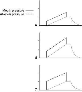
FIGURE 15.33 Mouth and alveolar pressures during inspiration with a constant flow generator. (A) Normal. (B) Decreased compliance. (C) Increased airway resistance. Alveolar volume remains constant because flow rate is constant. Decreased compliance results in an increased rate of increase of alveolar pressure; mouth pressure also increases more steeply, but the gradient between mouth and alveolar pressures remains normal. Increased airway resistance increases the mouth-alveolar pressure gradient.
Some ventilators generate a pressure rather higher than that required to inflate the lungs but not high enough to maintain constant flow throughout inspiration. The flow, volume and pressure changes within the lung are shown in Figure 15.34.
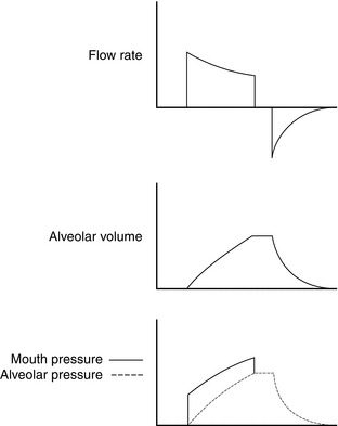
FIGURE 15.34 Pressure, flow and alveolar volume characteristics during inspiration with a ventilator with a moderately high internal pressure. At higher bellows pressures, and in a patient with normal compliance and airway resistance, the characteristics approximate to those of a constant flow generator (Fig. 15.33). At low bellows pressures, if compliance decreases or if airway resistance increases, the pattern is similar to that of a constant pressure generator.
Change from Inspiration to Expiration
This is termed ‘cycling’ and may be achieved in one of three ways:
Expiration
Usually, the patient is allowed to exhale to atmospheric pressure; flow rate decreases exponentially. Subatmospheric pressure should not be used during expiration as it induces closure of small airways and air trapping. PEEP may be applied in some circumstances (see Ch 45).
Delivery of Anaesthetic Gas
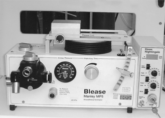
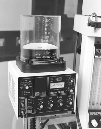
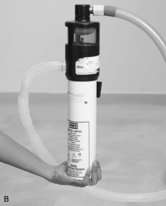
Some ventilators deliver a minute volume determined by a preset tidal volume and rate. When used in anaesthesia, these machines must be supplied with a flow rate of anaesthetic gases which equals or exceeds the minute volume delivered, otherwise air, or gas used to drive the ventilator, is entrained and delivered to the patient. Ventilators such as the Blease Manley ventilator (Fig. 15.35) are driven by the anaesthetic gas supply, can deliver only that gas, and divide it into predetermined tidal volumes (minute volume dividers).
Ventilators may be used to compress bellows in a separate system which contains anaesthetic gases (‘bag-in-a-bottle’); it is possible to provide IPPV in a circle system in this way. The bag-in-a-bottle ventilator (Fig. 15.36) consists of a chamber with a tidal volume range of 0–1500 mL (adult mode) or 0–400 mL (paediatric mode) and ascending bellows which accommodate FGF. The control unit has controls, displays and alarms and these may include tidal volume, respiratory rate, inspiratory to expiratory (I:E) ratio, airway pressure and an on/off/standby switch. Compressed air or oxygen is used as the driving gas. On entering the chamber, the compressed gas forces the bellows down, delivering the FGF within the bellows to the patient. The driving gas in the chamber and the FGF in the bellows remain separate.
The Penlon Nuffield 200 ventilator (Fig. 15.19) is an intermittent blower. It is a very versatile ventilator, which may be used in different age groups and using different breathing systems. The control unit consists of an airway pressure gauge (cmH2O), an on/off switch and controls to set inspiratory and expiratory time (seconds) and inspiratory flow rate (L s–1). Below the control unit, there is a connection for the driving gas (oxygen or air) and the valve block. A small tube connects the valve block to an airway pressure monitor and to a ventilator alarm. The valve block consists of a port for tubing to connect to the breathing system reservoir bag mount (Bain system) or the ventilator port (ADE system), an exhaust port which can be connected to the scavenging system and a pressure relief valve which opens at 6–7 kPa. With this standard valve, the ventilator is a time-cycled flow generator. The valve block can be changed to a paediatric Newton valve and this then converts the ventilator to a time-cycled pressure generator.
Older anaesthetic machine ventilators had a minimal number of controls, usually for minute volume, tidal volume, ventilator frequency and I:E ratio. The newer models resemble the critical care ventilators in the variable settings that are available. They perform self-tests which use dual processor technology when switched on, they have volume or pressure controlled ventilation modes, assisted spontaneous ventilation and electronically adjusted PEEP. They have sophisticated spirometry which compensates for factors such as leaks and patient compliance. They are suitable for a wider range of patients’ weight, and can deliver tidal volumes as low as 20 mL. The ventilator in the Primus Dräger (Fig. 15.2A) anaesthetic machine is an electronically controlled piston ventilator, which provides several modes of ventilation including volume control, pressure control, pressure support and volume mode autoflow. All these modes can be synchronized with patient effort and can have additional pressure support.
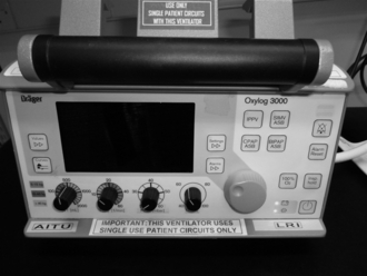
Transport Ventilators
There are several types of ventilator available for use during the transport of critically ill patients, such as the Pneupac VR1 and the Oxylog. The Oxylog 3000 (Fig. 15.37) and 3000Plus ventilators offer sophisticated ventilation in emergency situations and during transport. They are time-cycled, constant volume and pressure-controlled ventilators and deliver tidal volumes of 50 mL or more. They incorporate various modes of ventilation suitable for critically ill patients including IPPV, synchronized intermittent mandatory ventilation (SIMV) with adjustable pressure assist during spontaneous breathing, continuous positive airways pressure (CPAP) and biphasic positive airway pressure (BIPAP), apnoea ventilation for switching over automatically to volume-controlled ventilation if breathing stops, and non-invasive ventilation (NIV). Other features include monitoring of airway pressure and expiratory minute volume, integrated capnography and enhanced data connectivity.
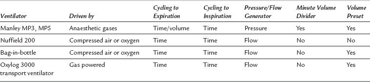
The characteristics of several common ventilators are summarized in Table 15.6.
High-Frequency Ventilation
High-frequency ventilation (HFV) may be defined as ventilation at a respiratory rate of greater than four times the resting respiratory rate of the subject. The different modes of HFV are shown in Table 15.7.
TABLE 15.7
Types of High-Frequency Ventilation
| Type of Ventilation | Rate of Ventilation (Cycles min–1) |
| High-frequency positive pressure ventilation (HFPPV) | 60–100 |
| High-frequency jet ventilation (HFJV) | 100–400 |
| High-frequency oscillation ventilation (HFOV) | 400–2400 |


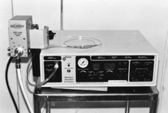
HFJV is used during some operations on the larynx, trachea or lung and in a small number of patients in the ICU. Gases should be humidified when using HFJV. Gas exchange may be unpredictable and the technique should not be used by the trainee without supervision. Figure 15.38 illustrates a type of ventilator used for HFJV.
Venturi Injector Device
The Venturi injector consists of a high-pressure oxygen source (at about 400 kPa from either the anaesthetic machine or direct from a pipeline), on/off trigger and connection tubing that can withstand high pressure. The Manujet (Fig. 15.39) is a newer design of a Venturi injector device. It has a dial to alter the driving pressure to suit the size of patient from a neonate to an adult. This is connected to the side of a rigid bronchoscope, to a transtracheal catheter or to a cannula inserted through the cricothyroid membrane. The injector is controlled manually. A 14 gauge cannula or a specially designed cannula (Fig. 15.40) inserted through the cricothyroid membrane may be used to ventilate using the Venturi injector device. A Venturi effect is created which entrains atmospheric air and allows intermittent insufflation of the lungs with oxygen-enriched air at airway pressures of 2.5–3.0 kPa. It is used in operations on the larynx, trachea or lung. Possible complications include barotrauma, gastric distension and awareness if inadequate quantities of intravenous anaesthetic drugs are administered. When Venturi injector devices are employed, it is essential to ensure that gas is able to leave the lungs though the upper airway during expiration.
SCAVENGING
The possible adverse effects of pollution on staff in the operating theatre environment are discussed in Chapter 20. The principal sources of pollution by anaesthetic gases and vapours include:
 discharge of anaesthetic gases from ventilators
 expired gas vented from the spill valve of anaesthetic breathing systems


Care in filling vaporizers. Great care should be taken not to spill volatile anaesthetic agent when a vaporizer is filled. The use of agent-specific connections (Fig. 15.10) reduces the risk of spillage. In some countries, vaporizers must be filled only in a portable fume cupboard.
Scavenging Apparatus
Anaesthetic gases vented from the breathing system are removed by a collecting system. A variety of purpose-built scavenging spill valves is available; an example of an adjustable pressure-limiting (APL) valve is shown in Figure 15.41. Waste gases from ventilators are collected by attaching the scavenging system to the expiratory port of the ventilator. Connectors on scavenging systems have a diameter of 30 mm to ensure that inappropriate connections with anaesthetic apparatus cannot be made.
Disposal systems may be active, semi-active or passive.
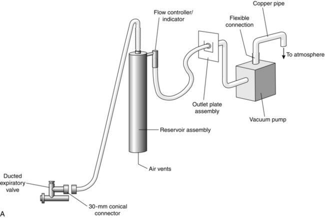
Active Systems
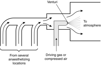
These employ apparatus to generate a negative pressure within the scavenging system to propel waste gases to the outside atmosphere. The system may be powered by a vacuum pump (Fig. 15.42) or a Venturi system (Fig. 15.43). The exhaust should be capable of accommodating 75 L min–1 continuous flow with a peak of 130 L min–1. Usually, a reservoir system (Fig 15.42B) is used to permit high peak flow rates to be accommodated. In addition, there must be a pressure-limiting device within the system to prevent the application of negative pressure to the patient’s lungs.
Passive Systems
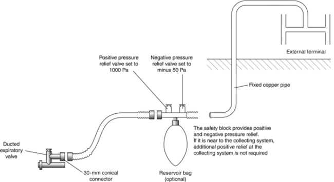
These systems vent the expired gas to the outside atmosphere (Fig. 15.44). Gas movement is generated by the patient. Consequently the total length of tubing must not be excessive or resistance to expiration is high. The pressure within the system may be altered by wind conditions at the external terminal; on occasions, these may generate a negative pressure, but may also generate high positive pressures. Each scavenging location should have a separate external terminal to prevent gases being vented into adjacent locations. Relief valves must be incorporated to prevent negative or high positive pressures within the system.
RESERVOIR BAGS
Reservoir bags are used in breathing systems. Their functions include:


LARYNGOSCOPES
Curved Blade
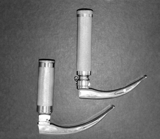
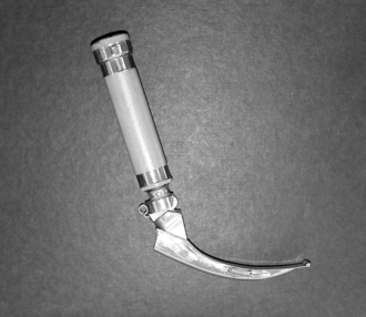
The most commonly used adult laryngoscope blade is the Macintosh curved blade, which is manufactured in several sizes (Figs 15.45, 15.46).
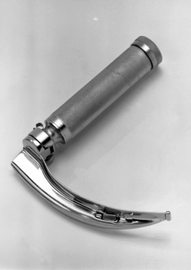
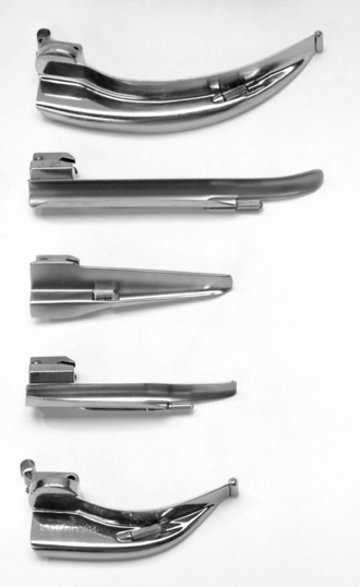
FIGURE 15.46 A selection of laryngoscope blades. From the top downwards: Macintosh adult blade, Miller adult blade, Soper infant blade, Wisconsin infant blade and Macintosh infant blade.
The tip of the laryngoscope blade is advanced carefully over the surface of the tongue until it reaches the vallecula (Ch 21, Fig. 21.3). The tip of the blade is rotated upwards and the laryngoscope lifted along the axis of the handle to lift the larynx; the incisor teeth must not be used as a fulcrum to lever the tip of the blade upwards. When the arytenoids and posterior part of the cords are seen, gentle pressure on the larynx using the right thumb, or provided by an assistant, may help to improve the view. Concerns have been raised about the possibility that multiple-use laryngoscopes may transfer between patients the prions thought to be responsible for causing variant Creutzfeldt–Jakob disease (vCJD), especially if used during surgery for tonsillectomy or adenoidectomy Therefore disposable laryngoscope blades are now used routinely. The quality of disposable laryngoscopes has improved enormously and is now indistinguishable from that of non-disposable devices.
Straight Blade
Straight-bladed laryngoscopes are useful adjuncts in safe airway management. However, they are not always as easy to use as curved blades. The technique of laryngoscopy is slightly different when a straight-bladed laryngoscope is used (see Fig. 21.3). Instead of placing the tip of the blade in the vallecula, it is advanced over the posterior border of the epiglottis, which is then lifted directly by the blade to provide a view of the larynx. This technique is useful particularly in babies, in whom the epiglottis is rather floppy and may obscure the view of the larynx if a curved blade is used. However, bruising of the epiglottis is more likely with a straight blade. The straight-bladed laryngoscopes available include the Miller, Magill, Soper and Wisconsin (Fig 15.46) laryngoscopes.
Laryngoscope Handle
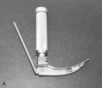
The standard handle may result in difficult laryngoscopy in obese patients, and in women with large breasts. Short handles are available for use in these situations (Fig. 15.47). The short handle has almost replaced the use of the Polio blade (Fig. 15.48) in obstetric practice.
The McCoy laryngoscope (Fig. 15.49A) is based on the standard Macintosh blade but has a hinged tip. This is operated by a lever mechanism attached to the handle. When the lever is pressed (Fig. 15.49B), the tip of the blade bends forward and this improves the view of the larynx.
Video Laryngoscopes
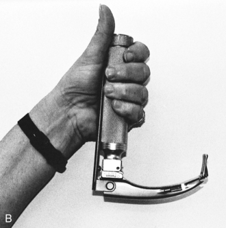
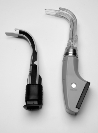
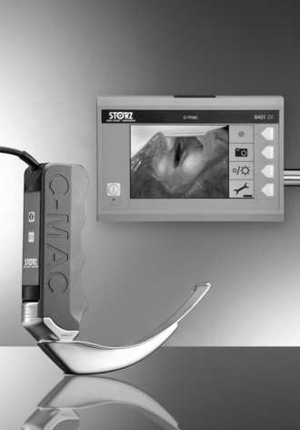
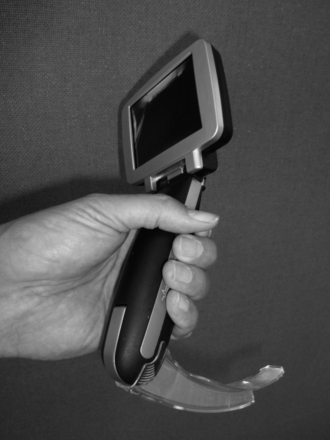
Traditional direct laryngoscopy depends on achieving a straight line of vision to the patient’s larynx. This requires alignment of the oral, pharyngeal and laryngeal axes. Videolaryngoscopes are a new class of laryngoscopes that have high resolution video cameras incorporated in the tip of a modified laryngoscope blade. The video image is relayed by either fibreoptic bundles, lenses or via cables to a dedicated LCD video display. Videolaryngoscopy allows the operator to see around the corners as the transmitted image is the view obtained from the tip of the laryngoscope blade. Aligning the three axes (oral, pharyngeal and laryngeal) and compression or distraction of tissues to achieve a line of sight are not required. With direct laryngoscopy, poor visualization of the glottic aperture is correlated with difficult intubation. The major difference with videolaryngoscopy when compared with conventional direct laryngoscopy is that it may be difficult to intubate the trachea despite a clear view of the glottis. Examples of videolaryngoscopes are those with a guiding channel such as the Pentax Airway scope and Airtraq (Fig. 15.50) and those without a guiding channel such as the Glidescope, McGrath and C-Mac (Fig. 15.51). The Venner AP Advance videolaryngoscope is a recent addition to the videolaryngoscope market (Fig. 15.52) in which the standard blade does not have a channel but the difficult airway blade does. The Airtraq is fully disposable whereas the other videolaryngoscopes have disposable blades but a reusable main unit. The C-Mac requires sterilization between uses.
Fibreoptic Laryngo/Bronchoscope
The fibreoptic scope (Fig. 15.53) is an endoscope which is used to view the upper and lower airway through either the nose or the mouth. The principle of the fibreoptic system is that light from a powerful external light source is transmitted through a flexible instrument and an image of the area is returned to an eyepiece or camera. The fibres which transmit the light have a diameter of approximately 20 μm and are made up of a central glass core coated with a thin layer of glass material with a lower refractive index. The light passing down the fibre is repeatedly reflected down the inner glass.
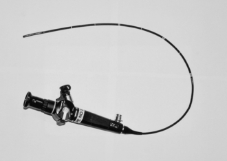
FIGURE 15.53 The fibreoptic intubating laryngoscope which consists of a control unit, insertion cord and a connector for a light guide.
The fibreoptic scope consists of a light source, a universal cord and light guide connector, a control unit, an eyepiece and an insertion tube. The light source (Fig. 15.54) is usually powered by mains electrical supply and contains either a xenon or a halogen lamp. The universal cord and light guide connector contain the light guide fibre bundle and transmits light from a light source to the fibreoptic bundle in the insertion tube. In some newer models, light is powered by a battery and this enables these scopes to be easily portable and be used in places outside the operating theatres, such as the emergency department.
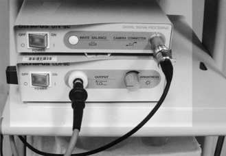
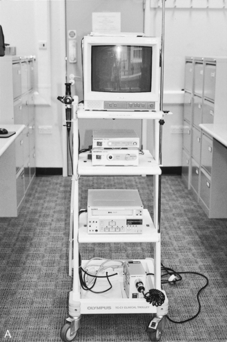
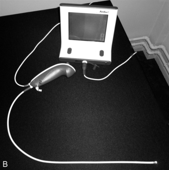
The eyepiece consists of the viewing lens and the dioptre adjustment ring. A camera can be attached to the eyepiece either to take photographs or to transmit the pictures to a television monitor (Figs 15.54 and 15.55A). A disposable fibreoptic scope (Ambuscope) is now available (Fig. 15.55B).
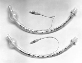
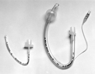
TRACHEAL TUBES
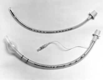
Most tracheal tubes are constructed of red rubber, silicone rubber or plastic. Red rubber tubes are reusable, although they may start to show signs of deterioration after 2–3 years. Today, disposable plastic tubes are the preferred choice (Fig. 15.56) as they eliminate the need to collect, clean, sterilize and check tubes after use. Plastic tubes are presented in a sterile pack and should be cut to an appropriate length before use. The plastic disposable tubes have a cuff and a pilot balloon with a self-sealing valve. The cuff may be inflated with air, nitrous oxide or saline. The internal diameter of the tube is marked on the side of the tube in millimetres and the length of the tube is marked along the length of the tube in centimetres. The tube also has a radio-opaque line running along its length. This enables the position of the tube to be determined on a chest X-ray.
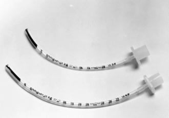
Plain Tubes
Uncuffed tubes are used in children (Fig. 15.57). A cuff is unnecessary to secure an airtight fit if the correct diameter of tube is selected, because the narrowest part of the airway is in the trachea at the level of the cricoid cartilage. However, the larynx is the narrowest part of the airway in the adult and a leak occurs if an uncuffed tube is used; in addition, there is a risk of aspiration of fluid from the pharynx into the trachea. Nasotracheal intubation is less traumatic if an uncuffed tube is used. The incidence of sore throat is not influenced by the presence of a cuff on the tracheal tube.
Shape of Tube
In most centres, a curved tracheal tube is used. These should be cut to the correct length as there is a risk of accidental intubation of a bronchus (usually the right main bronchus) if the tip is inserted too far. Some plastic tracheal tubes are preformed in shapes which either fit the pharyngeal contour or carry the proximal end of the tube away from the mouth (Fig. 15.58); the latter design is useful when surgery on the face or head is planned. The RAE (Ring, Adair and Elwyn) tubes have preformed curves and they can be used either orally or nasally (Fig. 15.59). RAE tubes may be cuffed or uncuffed. Care should be taken not to insert these preformed tubes too far as there is a risk of bronchial intubation.
Specialized Tubes
Reinforced flexometallic tubes are available in either uncuffed paediatric sizes or cuffed adult sizes (Fig. 15.60). These tracheal tubes are long and cannot be shortened because they have a fixed tracheal tube connector. Therefore, when inserting them into the trachea, care should be taken to avoid bronchial intubation. The adult cuffed tubes have two black rings and the paediatric uncuffed tubes have a black line at the distal end. These give guidance as to where the vocal cords should be, in order to avoid bronchial intubation.
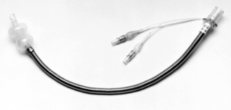
A flexible metal tube (Fig. 15.61) may be used during procedures that require the use of lasers in the airway; plastic tubes may ignite if struck by the laser beam. Some designs have two cuffs. This ensures a tracheal seal if the upper cuff is damaged by laser. An air-filled cuff may ignite if it is hit by a laser beam. Therefore it is recommended that the cuffs are filled with saline instead of air.
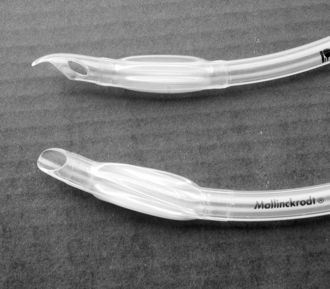
The Parker tube (Fig. 15.62) has a curved bevel on the inner curvature of the tube. The bevel therefore lies on the anterior aspect of the tube during insertion. The manufacturer claims that it is less likely than the conventional tube to cause trauma to the larynx or trachea, particularly during insertion over a bougie or fibreoptic laryngoscope.
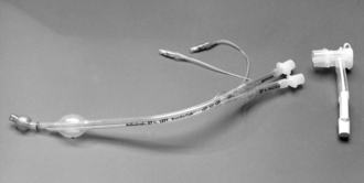
Double-lumen endobronchial tubes are used during thoracic surgery when there is a need for one lung to be deflated. They allow selective deflation of one lung whilst maintaining ventilation of the other lung. The older Robertshaw double-lumen tubes are made of red rubber and are therefore reusable. The disposable Bronchocath double-lumen tubes (Fig. 15.63), which are made of plastic, are used more commonly now.
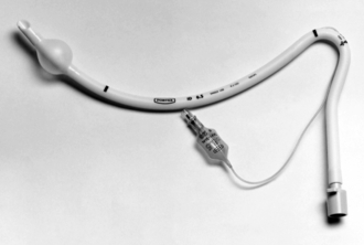
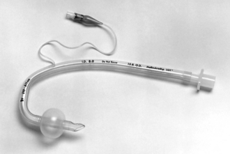
Laryngectomy tubes (Fig. 15.64) are designed to be inserted through a tracheostomy into the trachea to maintain the airway during surgery for laryngectomy. Because of its shape, the connection to the breathing system is some distance away from the surgical field and this gives the surgeon a relatively clear field in which to operate.
Tracheostomy Tubes
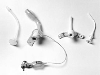
There are many types of tracheostomy tube. They may be cuffed or uncuffed. The proximal end of a tracheostomy tube has a standard 15-mm connector and there are two wings with slots to which the securing tape is attached (Fig. 15.65). Tracheostomy tubes have a replaceable inner cannula which facilitates insertion and is removed once the tracheostomy tube is in place.
Cricothyroidotomy Devices
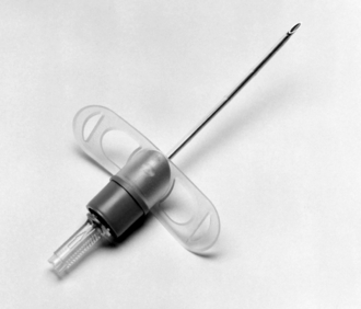
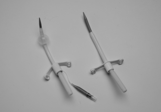
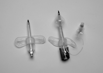
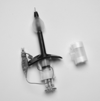
Cricothyroidotomy is the creation of an opening in the cricothyroid membrane in order to gain access to the airway either as an elective prophylactic cricothyroidotomy in an anticipated difficult airway or in an emergency ‘can’t intubate and can’t ventilate’ (CICV) scenario (see Ch 22). Cricothyroidotomy can be carried out using either a small cannula (Fig. 15.40), large bore cannula (4 mm or larger internal diameter) or surgically using a tracheostomy tube (6 mm or greater). There are several types of large bore cannulae available. The cuffed or uncuffed Melker kit (Fig. 15.66) uses a Seldinger technique. The cuffed or uncuffed VBM Quicktrach (Fig. 15.67) is a rigid pre-assembled cannula-over-needle device that is inserted as a single step procedure. The cuffed Portex cricothyroidotomy kit is also a rigid cannula-over-needle device, which is packaged as a pre-assembled kit with a scalpel and syringe (Fig. 15.68). It has a spring-loaded Veress needle with a blunt stilette. The Portex Minitrach II is a wire-guided kit which provides an uncuffed 4-mm airway through the cricothyroid membrane. It is designed for tracheal suction and not for an emergency situation because it is not easy to insert quickly.
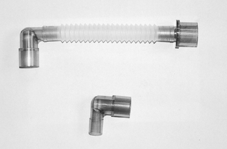
Connections
This is a flexible link between the breathing system and a tracheal tube, laryngeal mask airway, face mask or tracheostomy tube (Fig. 15.69). It may be made of rubber or plastic and some have a gas sampling port. The proximal end, which attaches to the breathing system, has a standard 22-mm connection and the distal end is a 15-mm connector. The length of catheter mounts varies from 45 to 170 mm.
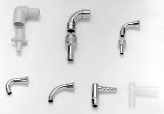
Tracheal Tube Connectors
Disposable 15-mm diameter connectors are provided with plastic disposable tubes; the diameter of the distal end is of an appropriate size to fit the internal diameter of the tube. Several older connections (Fig. 15.70) have been used with plastic or rubber tracheal tubes.
Angle Pieces
These are connectors which fit between the breathing system and the tracheal tube or mask (Fig. 15.69). They incorporate a 90° bend and have either 15- or 22-mm connectors at each end. Some angle pieces have a condenser humidifier, bacterial filter and a port for gas sampling incorporated into them (Fig. 15.30).
SUPRAGLOTTIC AIRWAY DEVICES (SADs)
The Classic LMA (cLMA)
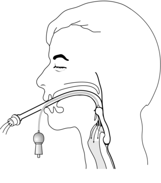
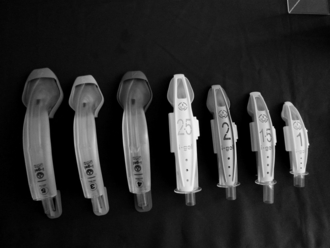
This device consists of a shortened conventional silicone tube with an elliptical cuff, inflated through a pilot tube, attached to the distal end (Fig. 15.71). The cuff, which resembles a miniature face mask, has been designed to form a relatively airtight seal around the posterior perimeter of the larynx (Fig. 15.72). A variety of sizes of cuff is available, ranging from size 1 which is used in the neonate to size 5 which is used in large adults. The mask is inserted and the cuff inflated until no air leak is detected. It is important to ensure that the maximum inflation volume is not exceeded (Table 15.8). The device is very effective in maintaining a patent airway in the spontaneously breathing patient. Positive pressure ventilation may be applied if necessary. The mask is not suitable for patients who are at risk from regurgitation of gastric contents (emergency surgery, hiatus hernia or history of reflux, and obesity) and should be used with caution if pharyngeal soiling is anticipated.
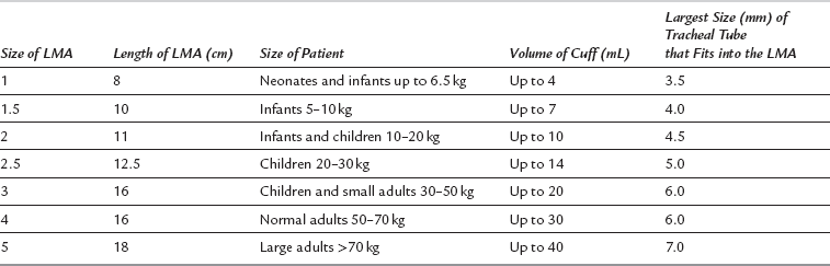
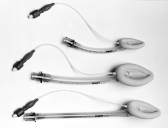
FIGURE 15.71 Laryngeal mask airways (LMAs). A paediatric size 2 mask, an adult size 4 mask and a size 3 reinforced LMA.
The flexible LMA differs from the standard LMA in that it has a flexible, wire reinforced tube. The size of the cuff is similar to that of the standard LMA but the tube is longer and narrower and therefore offers more resistance to breathing (Fig. 15.71). Because of the wire in the tube, it is unsuitable for use in the MRI unit. The classic LMA is reusable up to 40 times. However, a large selection of disposable LMAs manufactured by different companies is available and these are now used more commonly.
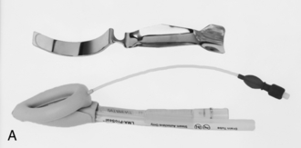
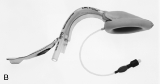
Second Generation SADs
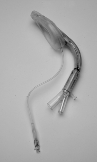
The Proseal LMA is a reusable LMA which has a drain tube, a posterior inflatable cuff, reinforced airway tube, integral bite block and an introducer (Fig.15. 73). The distal end must sit in the oesophageal inlet to ensure best performance. The drainage tube vents any gas leaking into the oesophagus as well as any fluid if regurgitation occurs and it can be used to insert an orogastric tube. The increased oesophageal and pharyngeal seal allows positive pressure ventilation to take place. The Pro-seal LMA is reusable up to 40 times and all its components are latex-free. It can be mounted on an introducer (Fig. 15.73B) which facilitates the insertion of the LMA Pro-seal into the patient’s mouth. The I-gel (Fig. 15.74) is a new single use SAD with a non-inflatable ‘cuff’ made of a soft thermoplastic elastomer. The ‘cuff’ is a preformed soft mould, which fits into the perilaryngeal structures. It has a narrow bore oesophageal drain tube, a short wide bore airway tube and an integral bite block. Both the Proseal and the I-gel come in adult and paediatric sizes. The Supreme LMA (SLMA) (Fig. 15.75) is the newest of the second generation SADs and it is sometimes described as a ‘single use Pro-seal LMA’. However, in reality, it has features of the Pro-seal LMA and the intubating LMA (ILMA). Its features include a large inflatable plastic cuff but no posterior cuff found in the Pro-seal LMA, an oesophageal drain tube, a preformed semi-rigid tube, an integral bite block and fins in the mask bowl to prevent epiglottic obstruction. It is made of PVC. Unlike a Pro-seal LMA, the SLMA does not require an introducer for insertion.
The Intubating LMA
The intubating LMA (ILMA) is an advanced form of the standard LMA (Fig. 15.76). It has a shorter tube and a metal handle. The handle permits single-handed insertion without moving the head and neck and without placing fingers in the mouth. It may be passed through an interdental gap as narrow as 20 mm. The mask floor has an elevating bar which replaces the two bars in the standard LMA. The caudal end of the bar is not fixed to the mask floor and this allows a tracheal tube to be passed in order to intubate the trachea. The ILMA is available in sizes 3, 4 and 5. The recommended cuff volumes are similar to the corresponding sizes of the standard LMA. The rigid curved airway has a standard 15-mm connector at the proximal end. The tube is wide enough to allow passage of a cuffed 8-mm tracheal tube. The ILMA is a reusable device which may be cleaned and sterilized up to 40 times but a single use version is now available.
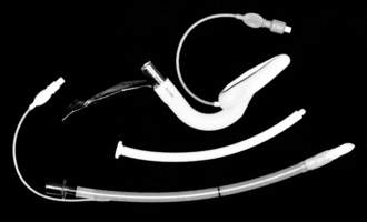
FIGURE 15.76 An intubating laryngeal mask airway (ILMA) with the silicone tracheal tube and the introducer.
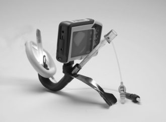
The C-Trach LMA (Fig. 15.77) is a variant of the ILMA with fibreoptic components integrated into the device to allow direct vision at intubation. It has a digital screen with a light source and digital camera. The lens lies behind the epiglottis elevator bar (EEB) and captures the image from the front of the mask aperture. The image is transmitted to the viewing screen.
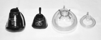
OTHER APPARATUS
These are designed to fit the face perfectly so that no leak of gas occurs, but without applying excessive pressure to the skin. An appropriate size of face mask must be selected to ensure a proper fit, but the smallest size possible should be used to minimize dead space. Disposable masks made of transparent material are available (Fig. 15.78). These allow the detection of vomitus or secretions.
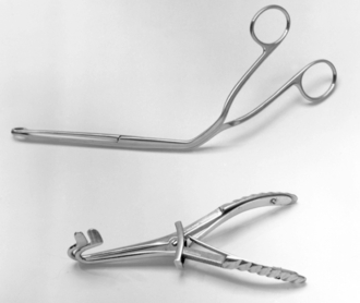
Intubating Forceps
The most commonly used intubating forceps are those designed by Magill (Fig. 15.79A). The instrument is employed to manipulate a nasotracheal or nasogastric tube through the oropharynx and into the correct position. A laryngoscope is used to obtain a view of the oropharynx.
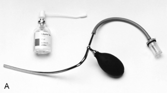
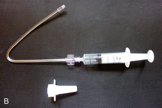
Laryngeal Spray
These are used to deposit a fine mist of local anaesthetic solution (usually lidocaine 4% or 10%) on the mucosa of the larynx and upper trachea (Fig. 15.80A and B). These sprays are particularly useful in applying local anaesthetic to the upper airway during awake fibreoptic intubation. The mucosal atomization device (MAD) is a single use atomizer which comes in two shapes, the oral and the nasal atomizer (Fig. 15.80B).
Mouth Gag
A mouth gag (Fig. 15.79B) may be used during dental anaesthesia and is required occasionally to open the mouth in patients with trismus, or if masseter spasm is present. It is positioned between the molar teeth and must be used with great care to avoid dental trauma.
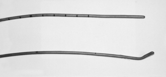
Bougie
If the larynx cannot be seen adequately during laryngoscopy, or if the tracheal tube cannot be manoeuvred into the laryngeal inlet, a bougie may be used as an aid to tracheal intubation. The lubricated bougie is inserted into the trachea to act as a guide for the tracheal tube. The tube should be rotated so that the bevel does not become lodged against the aryepiglottic fold. In a difficult intubation scenario, the correct type of bougie should be used (Fig. 15.81). The bougie with a curved tip at the end is designed to assist in this situation whereas the straight-ended bougie is intended for endotracheal tube exchange only. Disposable bougies are now available but their efficacy over the reusable ones is yet to be demonstrated. The Eschmann (gum elastic) multiple-use bougie has the highest success rate, least likelihood of causing trauma and has reliable and clinically tested signs of confirmation of tracheal placement when compared with either the Frova single-use intubation introducer or the Portex single-use introducer.
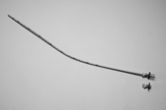
The Aintree Intubating Catheter (AIC)
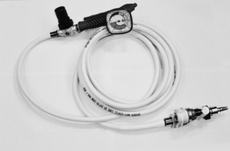
This is a 56-cm hollow catheter with special adapters that connect to either a 15-mm connector for use with conventional anaesthetic circuits or a Luer lock for use with a jet ventilator (Fig. 15.82). The catheter has an internal diameter of 4.8 mm which allows it to be preloaded over a fibreoptic scope. The AIC is used for LMA-assisted orotracheal fibreoptic intubation. However, it should not be used without prior training as failure to follow the correct instructions can result in serious morbidity or mortality.
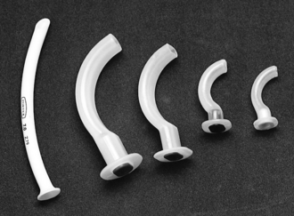
Airways
An oropharyngeal airway (Guedel airway, Fig. 15.83) may be required to prevent obstruction caused by the tongue or collapse of the pharynx in the patient without a tracheal tube. A nasopharyngeal airway (Fig. 15.83) is tolerated better during light anaesthesia and may also be used if it is difficult to insert an oropharyngeal airway, e.g. trismus. However, the use of nasopharyngeal airways may be associated with significant bleeding from the nose.
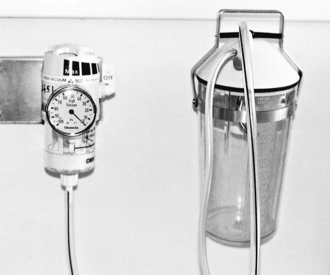
Suction Apparatus
The suction unit consists of a reservoir jar, bacterial filter, vacuum control regulator and a vacuum gauge (Fig. 15.84). The reservoir jar is graduated so that the volume of aspirate may be estimated. It contains a cut-off valve. The cut-off valve has a float that rises as the fluid level increases and shuts off the valve when the reservoir jar is full. This prevents liquid from the suction jar entering the suction system. There is a bacterial filter between the cut-off valve and the suction control unit to prevent air that has been contaminated during passage through the apparatus infecting the atmosphere when it is blown out. The filter also traps any particulate or nebulized matter. Filters should be changed at regular intervals.
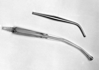
The suction reservoir jar is connected to the patient via a suction tubing and either a Yankauer hand piece (Fig. 15.85) or suction catheters.
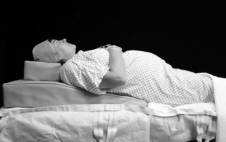
Head-Elevating Laryngoscopy Position Devices
Many studies have been conducted over the last ten years investigating the effect of a head-elevated position or ramping on laryngeal view. An imaginary line drawn between the patient’s sternal notch should be in line with the auditory meatus in order to maximize the laryngeal view. Ramping or the head-elevated laryngoscopy position has been shown to improve the laryngeal view, particularly in obese patients. This has led to the development of devices such as the Oxford Head-Elevating Laryngoscopy Pillow (Oxford HELP) (Fig. 15.86). This device can be inserted and removed much faster and with less difficulty than using standard hospital pillows.
Al-Shaikh, B., Stacey, S. Essentials of anaesthetic equipment, third ed. London: Churchill Livingstone; 2010.
Association of Anaesthetists of Great Britain and Ireland. Infection control in anaesthesia 2. London: AAGBI; 2008.
Association of Anaesthetists of Great Britain and Ireland. Checking anaesthetic equipment. Anaesthesia. 2012;67:660–668.
Davey, A., Diba, A. Anaesthetic equipment, fifth ed. London: WB Saunders; 2005.
Dorsch, J.A., Dorsch, S.E. Understanding anaesthetic equipment, fifth ed. London: Williams and Wilkins; 2008.
Gabbott, B.M. Recent advances in airway technology. BJA CEPD Reviews. 2001;1:76–80.
Patel, B., Frerk, C. Large bore cricothyroidotomy devices. Continuing Education in Anaesthesia, Critical Care and Pain. 2008;8:157–160.
Popat, M. Difficult airway management, first ed. Oxford: Oxford University Press; 2009.
Sabir, N., Ramachandra, V. Decontamination of anaesthetic equipment. Continuing Education in Anaesthesia, Critical Care and Pain. 2004;4:103–106.
Sinclair, C., Thadsad, M.K., Barker, I. Modern anaesthetic machines. Continuing Education in Anaesthesia, Critical Care and Pain. 2006;6:75–78.