Procedure 82 Radioulnar Ligament Reconstruction for Chronic Distal Radioulnar Joint Instability
 See Video 60: Reconstruction for Chronic Volar Subluxation of the Ulna
See Video 61: Distal Radioulnar Joint Ligament Reconstruction for Ligamentous Instability

Examination/Imaging
Clinical Examination
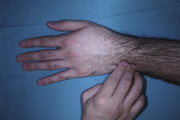
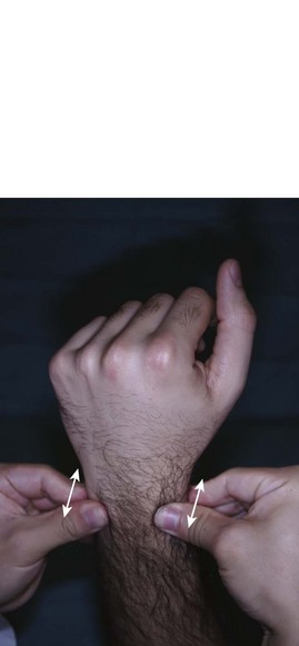
 DRU joint instability may coexist with other causes of ulnar-sided wrist pain. These include extensor carpi ulnaris (ECU) tendinitis, flexor carpi ulnaris (FCU) tendonitis, ECU subluxation, ulnar impaction syndrome, lunotriquetral (LT) instability, and pisotriquetral arthritis. It is important to consider these conditions before attributing the symptoms to DRU joint instability. The following clinical tests are suggestive of DRU joint instability:


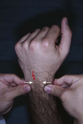
Imaging
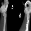
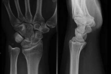
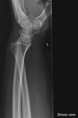
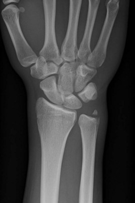
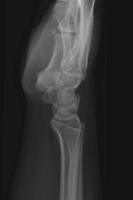
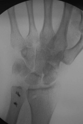
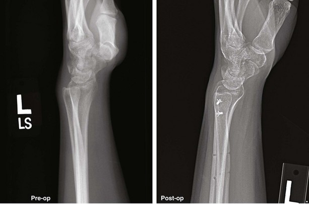
 A posteroanterior view radiograph may show widening of the DRU joint, and the lateral view demonstrates the ulnar head dorsal or volar to the radius (Fig. 82-4). A weighted lateral view (taken with patient holding 5 to 8 pounds of weight) can be used to demonstrate the instability that occurs only on loading (Fig. 82-5). Other indirect signs of instability include a basal ulnar styloid fracture (Fig. 82-6) and a displaced fleck fracture from the fovea.

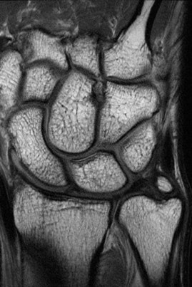
 Magnetic resonance imaging (Fig. 82-7) and arthroscopy are useful in assessment of the triangular fibrocartilage complex (TFCC) and in ruling out other causes of ulnar-sided wrist pain.
Pearls
To ensure that the lateral radiograph is adequate, the index, long, and ring metacarpals; the proximal pole of the scaphoid on the lunate; and the radial styloid in the center of the lunate should all be superimposed on one another. Additionally, the palmar surface of the pisiform should be visible midway between the palmar surfaces of the distal pole of the scaphoid and the capitate (Fig. 82-8).
Surgical Anatomy
 The DRU joint is formed by the sigmoid notch of the radius and the ulnar head. It is the distal pivot for pronosupination. This joint is stabilized predominantly by ligaments, the fibrocartilaginous lips at the rim of the sigmoid notch, and the shape of the sigmoid notch in the coronal plane.
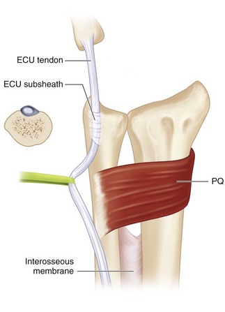
 The stabilizers of the DRU joint include the TFCC, pronator quadratus (PQ), ECU, and interosseous membrane (Fig. 82-9).

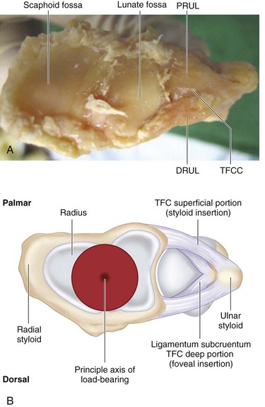
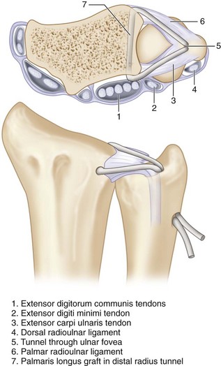
 The palmar and dorsal radiolulnar ligaments are the main stabilizers of the DRU joint. These ligaments extend from the palmar and dorsal distal margins of the sigmoid notch and converge in a triangular configuration to attach to the ulna. Each radioulnar ligament divides in the coronal plane into a deep limb that inserts into the fovea and a superficial limb that inserts into the midportion of the ulnar styloid (Fig. 82-10).
Positioning
 The patient is positioned supine with the affected extremity on a hand table. The procedure is performed under tourniquet control.
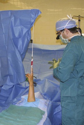
 The arm is strapped to the arm board using a soft roll and secured with tape. The forearm is held vertical and in neutral alignment using “Chinese finger traps” similar to the position used in wrist arthroscopy. This position is maintained by a traction tower using a 5-lb weight (Fig. 82-11)

Exposures
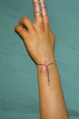
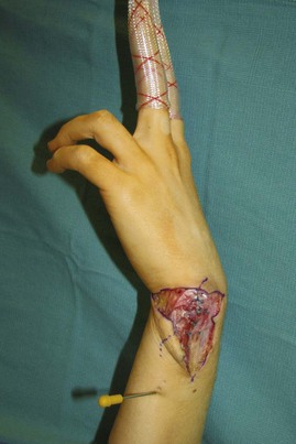
 A Y-shaped incision centered over the ulnar head is made on the ulnar border of the distal forearm. The vertical limb extends 5 cm proximal to the ulnar head along the ulnar border of the forearm. The volar limb extends to the pisiform, and the dorsal limb extends to the Lister tubercle (Fig. 82-12).
 Three skin flaps (distal, volar, and dorsal) are raised in a plane superficial to the tendons and extensor retinaculum (Fig. 82-13).
Procedure
Step 1: Development of Volar Plane
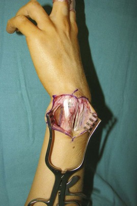
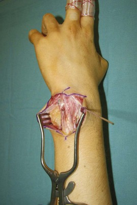
 The FCU and the ulnar neurovascular bundle are identified. A plane is developed deep to these structures to expose the ulnar styloid, palmar surface of the ulnar head, and palmar rim of the sigmoid fossa (Fig. 82-14)

Step 1 Pearls
The articular surface of the sigmoid notch and ulnar head are examined for arthritic changes. Ligament reconstruction can be performed only if there is no evidence of DRU joint arthritis. If arthritis is present, a salvage procedure, such as the Sauve-Kapandji or Darrach procedure, or a hemiresection should be considered.
Step 2: Development of Dorsal Plane
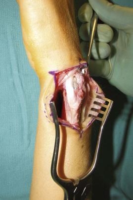
 The extensor retinaculum is divided longitudinally over the sixth compartment, and the ECU subsheath is identified. The sheath is divided along the ulnar border of the ECU, and the ECU is retracted ulnarly. This exposes the dorsal capsular tissues immediately radial to the ulnar styloid. The capsular tissue is divided longitudinally to expose the dorsal surface of the ulnar fovea (Fig. 82-15).

Step 3: Harvest of Palmaris Longus Tendon Graft
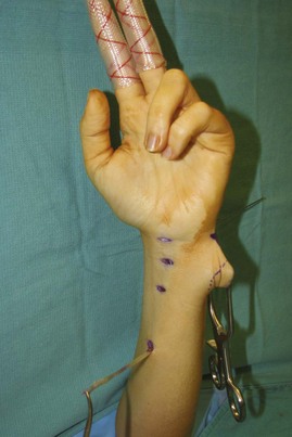
 A PL tendon graft is harvested by three separate 1-cm transverse incisions in the forearm (Fig. 82-16).
Step 4: Creation of Bone Tunnel in the Radius
 A K-wire is passed about 1 cm from volar edge of the sigmoid fossa to a similar position on the dorsal edge of the sigmoid fossa. This is done under fluoroscopic guidance to ensure that the wire is not within the radiocarpal or the radioulnar joints.

Step 4 Pearls
The tunnel should be made at a sufficient distance (1 cm) from both the distal and the ulnar articular surface of the radius to avoid a fracture of the bone during creation of the tunnel or passage of the tendon graft.
It is better to make the tunnel from volar to dorsal because the entry point can be controlled and inadvertent injury to the median nerve prevented.
Step 5: Passage of Tendon Graft
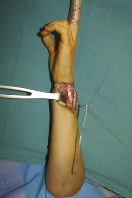
 A 25-gauge stainless steel wire loop is fashioned and passed from dorsum to the volar surface through the bone tunnel in the radius. One end of the PL tendon graft is fixed to the wire by twisting the loop. The wire is pulled back to bring the tendon out of the dorsal portion of the tunnel (Fig. 82-17).

Step 5 Pearls
Moistening the tendon graft will prevent it from desiccating and make passage through the bone tunnels easier.
A hemostat should be attached to the free end of the tendon graft before pulling on the wire loop to pass the tendon through the bone tunnel in the radius. This will prevent the entire tendon from coming out through the bone tunnel.
Step 6: Creation of Bone Tunnel in Ulna
 A K-wire is passed obliquely from the fovea to exit at the ulnar border of the ulna about 1.5 cm proximal. The position of the wire is confirmed by intraoperative fluoroscopy. A 2.3- to 3-mm cannulated drill is passed over the above K-wire to make a bone tunnel within the ulna, and the K-wire is removed (Fig. 82-18).

Step 7: Passage of Tendon Graft through Ulna
 Both ends of the tendon graft are passed through the bone tunnel in the ulna using a 25-gauge stainless steel wire loop as described previously. The wire loop is passed from outside-in to emerge at the fovea, both tendon ends are grasped, and the wire is pulled out to bring the tendon ends at ulnar border of the ulna.
 This step can be omitted, if a bone tunnel has been not been made in the ulna.
Step 8: Reduction and Pinning of DRU Joint
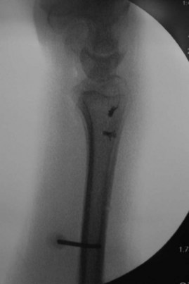
 The forearm is held in neutral rotation, the ulnar head is reduced into the sigmoid fossa, and the reduction is maintained with one or two 0.045-inch K-wires passed from the ulna to the radius about 4 to 5 cm proximal to the ulnar styloid.
 The position of the wires is confirmed by intraoperative fluoroscopy (Figs. 82-19 and 82-20).
Step 9: Suture Fixation of Reconstructed Ligaments
 If both ends of the tendon graft are passed through a bone tunnel in the ulna, they are looped around the shaft of the ulna and sutured to each other, and a bone anchor placed proximal to the ulnar exit hole, as tightly as possible.
 If an ulnar bone tunnel has not been used, two or more bone anchors are passed at the fovea and on either side of the ulnar styloid. The tendon graft is looped around the shaft of the ulna and sutured to each other and to the bone anchors as tightly as possible (Fig. 82-21).


Postoperative Care and Expected Outcomes
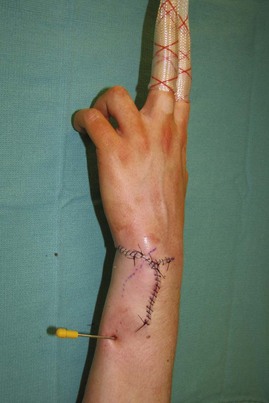
 The wound is inspected 2 weeks after surgery, and all sutures are removed. A thermoplastic Muenster-type splint that keeps the forearm and wrist in neutral position is provided. The patient is allowed active finger motion only.

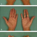
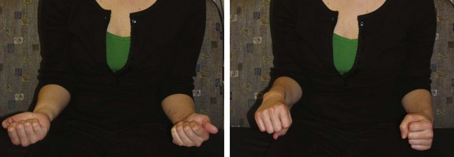
 Up to 80% to 90% of patients have reported resolution of pain and restoration of DRU joint stability after ligament reconstruction. However, an average of 10 to 20 degrees of pronation and supination range of motion is lost (Figs. 82-23 and 82-24).
Adams BD, Berger RA. An anatomic reconstruction of the distal radioulnar ligaments for posttraumatic distal radioulnar joint instability. J Hand Surg [Am]. 2002;27:243-251.
Gofton WT, Gordon KD, Dunning CE, et al. Comparison of distal radioulnar joint reconstructions using an active joint motion simulator. J Hand Surg [Am]. 2005;30:733-742.
Teoh LC, Yam AKT. Anatomic reconstruction of the distal radioulnar ligaments: long-term results. J Hand Surg [Br]. 2005;30:185-193.