[level-membership-for-surgery-category]
Procedure 81 Ulnar Shortening Osteotomy
 See Video 59: Ulnar Shortening Osteotomy


Examination/Imaging
Clinical Examination
 Patients with ulnar impaction syndrome present with ulnar-sided wrist pain, swelling, and limitation of motion. This may coexist with other causes of ulnar-sided wrist pain, including triangular fibrocartilage complex (TFCC) injuries, distal radioulnar (DRU) joint instability, and lunotriquetral ligament injuries, among others. It is important to consider these conditions before attributing the symptoms to ulnar impaction syndrome, particularly among patients with negative ulnar variance.

Imaging
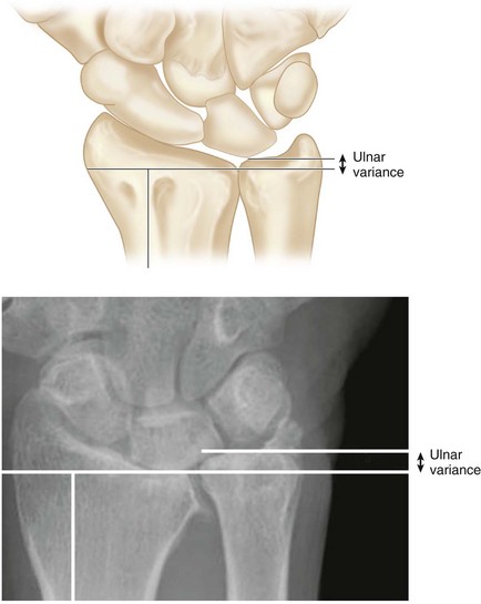
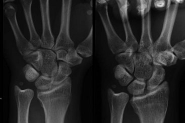
 A neutral rotation posteroanterior view will help determine ulnar variance. Ulnar variance describes the relative positions of the distal articular surface of the radius and ulna. When both the distal radius and the distal ulna are at the same level, it is called neutral variance (12%). If the distal ulna is distal to the radius, it is called positive ulnar variance (55%), and if the distal ulna is proximal to the radius, it is called negative ulnar variance (33%). A variance of −2 mm to +2 mm is considered normal (Fig. 81-3). Ulnar variance increases with pronation (up to 1 mm) and with forceful grip (up to 2 mm) (Fig. 81-4).
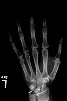
 A positive ulnar variance is associated with ulnar impaction syndrome. Other radiological features include cystic changes and sclerosis in the ulnar corner of the lunate, triquetrum, and radial portion of the distal ulnar head (Fig. 81-5).
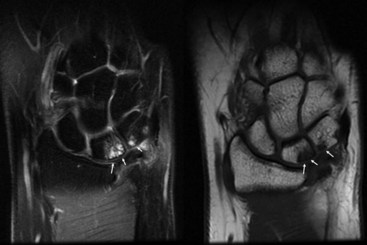
 Magnetic resonance imaging can identify degenerative changes related to ulnar impaction syndrome earlier than plain radiographs because it can reveal subchondral bone marrow edema and early chondromalacia on fat-suppressed, T2-weighted and short T1-weighted inversion recovery images (Fig. 81-6).
 Wrist arthroscopy is the most accurate modality for diagnosis of ulnar impaction syndrome. Any other associated pathology of the wrist can also be evaluated and the condition of the TFCC noted. Palmer has proposed a classification of degenerative TFCC tears (Table 81-1).
| Type 1 | Traumatic Lesions |
| 1a | Isolated central disk perforation |
| 1b | Peripheral ulnar-sided tear of TFCC (with or without ulnar styloid fracture) |
| 1c | Distal TFCC disruption from distal ulnocarpal ligaments |
| 1d | Radial TFCC disruption ± sigmoid notch fracture |
| Type 2 | Degenerative Lesions |
| 2a | TFCC wear |
| 2b | 2a with lunate and/or ulnar chondromalacia |
| 2c | TFCC perforation with lunate and/or ulnar chondromalacia |
| 2d | 2c + lunotriquetral ligament perforation |
| 2e | 2d + ulnocarpal arthritis |
Surgical Anatomy
 The radiocarpal joint transmits 82% of the load across the wrist, whereas the ulnocarpal joint transmits the remaining 18% in a neutral ulnar wrist. In subjects with a 2.5-mm positive ulnar variance, the load transmission across the ulna increases to 42%. This substantial increase in load in a positive ulnar wrist puts it at a high risk for ligamentous and articular degeneration. Increased dorsal tilt of the radius can further exacerbate loading onto the ulnar wrist. On the contrary, in a 2.5-mm negative ulnar variance wrist, the load transmission decreases to 4.3%. This is the basis for the ulnar shortening osteotomy.


Exposures
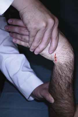
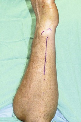
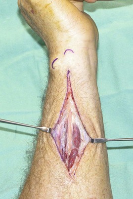
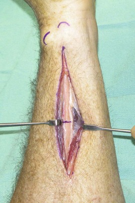
 A 10-cm longitudinal incision is made on the subcutaneous border of the ulna beginning 1 to 2 cm proximal to the ulnar styloid (Fig. 81-7). The flexor carpi ulnaris (FCU) and extensor carpi ulnaris (ECU) are identified, and the interval between them is developed to expose the subcutaneous border of the ulna (Fig. 81-8).

Pitfalls
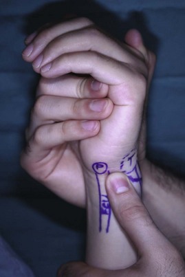
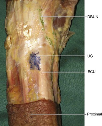
Care should be taken to avoid the dorsal cutaneous branch of the ulnar nerve. It arises about 8 cm proximal to the ulnar styloid, passes below the FCU, and runs in an oblique course toward the ulnar styloid (Fig. 81-9).
The compression plate can be placed on the volar surface or the subcutaneous dorsal surface of the ulna. Placement on the subcutaneous dorsal surface is easier, but the plate is palpable, can cause soft tissue irritation, and usually requires removal at a later date. Placement on the volar surface avoids these complications but requires more dissection and soft tissue stripping, which may result in a higher incidence of nonunion. The senior author prefers to place the plate on the subcutaneous dorsal surface of the ulna.
Procedure
Step 1: Preparation of Osteotomy Site


Step 2: Placement of Saw Guide
 The selected plate is placed on the exposed dorsal subcutaneous surface of the ulna. The distal end of the plate should be 3 to 4 cm from the ulnar styloid, and the long elliptical hole on the plate should be distal to the proposed osteotomy site. The position of the second plate hole (from proximal) is marked on the bone. The plate is then removed.
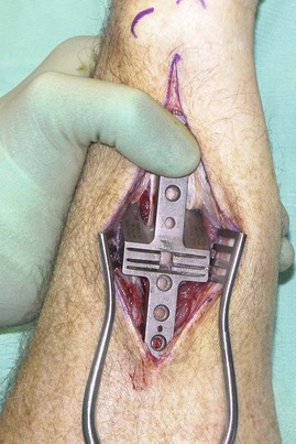
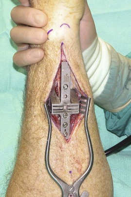
 The saw guide is placed such that the second hole on the guide (from proximal) is lined up with the previously marked second hole on the plate (Fig. 81-11).
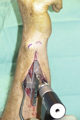
 The saw guide is held manually and using a straight drill guide, a 2.5-mm drill is used to make a hole through the second hole on the guide. The depth of the hole is measured, the hole is tapped with a 3.5-mm tap, and a 3.5-mm cortical screw is inserted (Fig. 81-12). This procedure is repeated for the fourth and then the third holes on the saw guide (Fig. 81-13).
Step 3: Performing Oblique Osteotomy
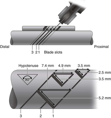
 The amount of bone removed should equal the amount of positive ulnar variance plus the amount of negative ulnar variance desired as measured on the neutral posteroanterior view. In general, about 2 to 2.5 mm of negative ulnar variance is desired, and typically a 3- to 5-mm segment of bone is resected. The anticipated shortening in a Rayhack system depends on the slots that are used to make the parallel oblique osteotomy cuts (slots 1 and 2 = 3.5 mm; slots 2 and 3 = 4.9 mm; and slots 1 and 3 = 7.4 mm) (Fig. 81-14).
 The saw is used to make the distal cut first, followed by the proximal cut.
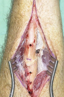
 The 3.5-mm screws holding the saw guide, and the saw guide and the segment of excised bone are removed in sequence (Fig. 81-15).
Step 4: Application of Plate, Compression Device, and Compression of Osteotomy
 The previously selected prebent six-hole low-profile plate (or a six-hole LC-DCP) is placed over the ulna, and a 3.5-mm screw is passed into the second hole of the plate (first hole on the ulna) to fix the plate to the ulna.
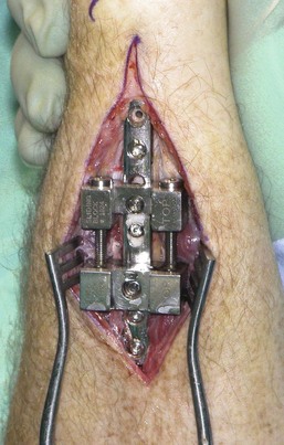
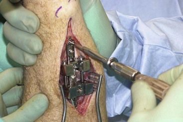
 The compression device is then placed over the plate and secured in position to the plate and the ulna by passing a screw through the third hole of the plate (first hole of compression device and second hole on ulna). This screw should be 4 mm longer than the previously passed screw (Fig. 81-16).
 Another screw is passed through the sliding block of the compression device onto the elliptical hole on the plate and the third hole on the bone. This screw is not tightened fully (Fig. 81-17).

Step 5: Placement of Interfragmentary Lag Screw


Step 6: Final Fixation of Plate
 A hand-held drill guide and a 2.5-mm drill bit are used to make a hole through the fifth hole of the plate. This hole is measured and tapped, and 3.5-mm cortical screw is placed.

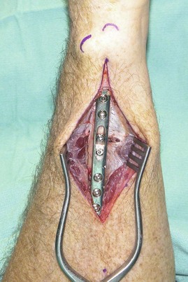
 The compression device is removed, and the original screws for holes 3 and 4 are reinserted (Fig. 81-18).
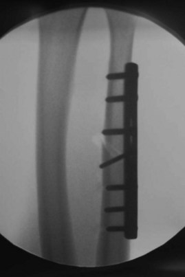
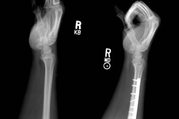
 Intraoperative fluoroscopy is used to confirm the position of the plate and screws (Fig. 81-19).

Postoperative Care and Expected Outcomes


Baek GH, Chung MS, Lee YH, et al. Ulnar shortening osteotomy in idiopathic ulnar impaction syndrome. J Bone Joint Surg [Am]. 2006;88:212-220.
Chen NC, Wolfe SE. Ulna shortening osteotomy using a compression device. J Hand Surg [Am]. 2003;28:88-93.
Kitzinger HB, Karle B, Low S, Krimmer H. Ulnar shortening osteotomy with a premounted sliding-hole plate. Ann Plast Surg. 2007;58:636-639.
[/level-membership-for-surgery-category][not-level-membership-for-surgery-category]
Procedure 81 Ulnar Shortening Osteotomy
See Video 59: Ulnar Shortening Osteotomy
Examination/Imaging
Clinical Examination
Patients with ulnar impaction syndrome present with ulnar-sided wrist pain, swelling, and limitation of motion. This may coexist with other causes of ulnar-sided wrist pain, including triangular fibrocartilage complex (TFCC) injuries, distal radioulnar (DRU) joint instability, and lunotriquetral ligament injuries, among others. It is important to consider these conditions before attributing the symptoms to ulnar impaction syndrome, particularly among patients with negative ulnar variance.
Imaging
A neutral rotation posteroanterior view will help determine ulnar variance. Ulnar variance describes the relative positions of the distal articular surface of the radius and ulna. When both the distal radius and the distal ulna are at the same level, it is called neutral variance (12%). If the distal ulna is distal to the radius, it is called positive ulnar variance (55%), and if the distal ulna is proximal to the radius, it is called negative ulnar variance (33%). A variance of −2 mm to +2 mm is considered normal (Fig. 81-3). Ulnar variance increases with pronation (up to 1 mm) and with forceful grip (up to 2 mm) (Fig. 81-4).
A positive ulnar variance is associated with ulnar impaction syndrome. Other radiological features include cystic changes and sclerosis in the ulnar corner of the lunate, triquetrum, and radial portion of the distal ulnar head (Fig. 81-5).
Magnetic resonance imaging can identify degenerative changes related to ulnar impaction syndrome earlier than plain radiographs because it can reveal subchondral bone marrow edema and early chondromalacia on fat-suppressed, T2-weighted and short T1-weighted inversion recovery images (Fig. 81-6).
Wrist arthroscopy is the most accurate modality for diagnosis of ulnar impaction syndrome. Any other associated pathology of the wrist can also be evaluated and the condition of the TFCC noted. Palmer has proposed a classification of degenerative TFCC tears (Table 81-1).
| Type 1 | Traumatic Lesions |
| 1a | Isolated central disk perforation |
| 1b | Peripheral ulnar-sided tear of TFCC (with or without ulnar styloid fracture) |
| 1c | Distal TFCC disruption from distal ulnocarpal ligaments |
| 1d | Radial TFCC disruption ± sigmoid notch fracture |
| Type 2 | Degenerative Lesions |
| 2a | TFCC wear |
| 2b | 2a with lunate and/or ulnar chondromalacia |
| 2c | TFCC perforation with lunate and/or ulnar chondromalacia |
| 2d | 2c + lunotriquetral ligament perforation |
| 2e | 2d + ulnocarpal arthritis |
Surgical Anatomy
The radiocarpal joint transmits 82% of the load across the wrist, whereas the ulnocarpal joint transmits the remaining 18% in a neutral ulnar wrist. In subjects with a 2.5-mm positive ulnar variance, the load transmission across the ulna increases to 42%. This substantial increase in load in a positive ulnar wrist puts it at a high risk for ligamentous and articular degeneration. Increased dorsal tilt of the radius can further exacerbate loading onto the ulnar wrist. On the contrary, in a 2.5-mm negative ulnar variance wrist, the load transmission decreases to 4.3%. This is the basis for the ulnar shortening osteotomy.
