Procedure 68 Percutaneous Screw Fixation of Scaphoid Fractures
 See Video 50: Screw Fixation of Scaphoid Fracture


Examination/Imaging
Clinical Examination
 Fractures of scaphoid are frequently missed in the emergency room or dismissed by the patient as a wrist sprain. Thus, the physician must have a high suspicion in young and middle-aged patients who present with wrist pain after a fall on an outstretched hand.
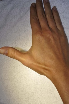
 General dorsoradial edema and focal snuffbox tenderness are highly suggestive of an acute scaphoid fracture (Fig. 68-1).
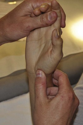
 The distal pole of scaphoid may be tender to palpation (Fig. 68-2).

Imaging
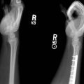
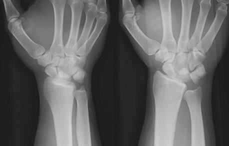
 The initial posteroanterior (PA) and lateral radiographs may fail to demonstrate a scaphoid fracture (Fig. 68-3). The incidence of false-negative radiographs for acute fractures has been shown to be up to 25%.
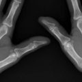
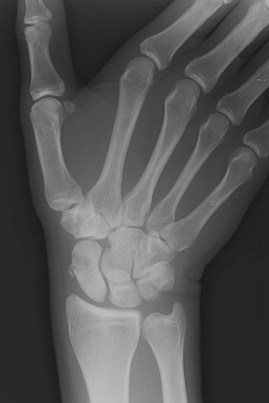
 Additional helpful radiographic views include (1) clenched-fist PA, which can exaggerate a fracture deformity and help make a diagnosis; (2) ulnar-deviated PA that positions the scaphoid in extension showing the waist more clearly (Fig. 68-4); and (3) pronated oblique view.
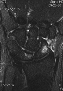
 Magnetic resonance imaging (MRI) is highly sensitive for making the diagnosis—cortical disruption with bone marrow edema is diagnostic. For chronic injuries, MRI is valuable in assessing proximal pole vascularity (Fig. 68-5).

Surgical Anatomy
 The scaphoid is the largest bone in the proximal carpal row, and its axis lies about 45 degrees to the longitudinal axis of the wrist.


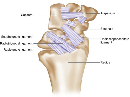
 Multiple intrinsic and extrinsic ligaments attach to the scaphoid (Fig. 68-6). The most important is the radioscaphocapitate, which provides an axis on which the scaphoid flexes.

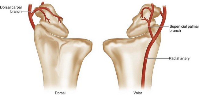
 A dorsal branch of the radial artery provides 70% to 80% of the blood supply (Fig. 68-7).
 A second nutrient artery enters volarly and supplies only the distal pole.

Positioning


Exposures


Procedure
Step 1: Dorsal Approach—Finding the Starting Point
 The wrist is flexed 60 degrees over a rolled towel bump.
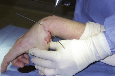
 To find the starting point, the guidewire is introduced through the skin about 1 cm distal to the Lister tubercle and advanced to just over the lip of the dorsal distal radius (Fig. 68-8).
 The starting position at the proximal ulnar edge of the scaphoid is found fluoroscopically (Fig. 68-9).

Step 1 Pearls
Use the minifluoroscope and a K-wire to determine the alignment of the scaphoid axis on PA and lateral views. Draw out the anticipated trajectory of the screw on the skin with a marking pen as a guide for the wire placement.
It is sometimes helpful to first use a 22-gauge needle to find the appropriate starting point and trajectory.
Step 2: Reducing the Fracture (if Necessary)
 If the fracture is displaced, 0.062-inch K-wires can be inserted dorsally into each fragment and used as joysticks to facilitate the reduction.
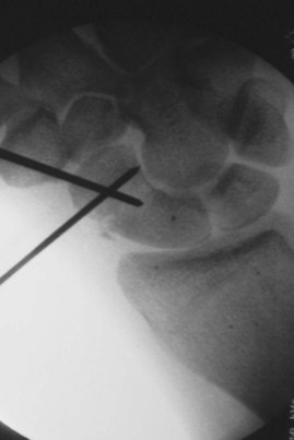
 Alternatively, the two K-wires can be inserted in the distal fragment—one dorsally and one radially—to reduce the fracture (Fig. 68-10).
Step 2 Pitfalls
Scrutinize the fluoroscopic images to ensure that the fracture is reduced on multiple views. Slight incongruity on one view might represent marked displacement on another view.
Be wary of the radial artery when placing the percutaneous reduction wires because the radial artery passes through the snuffbox.
Step 3: Placing the Guidewire
 With the fracture reduced, carefully advance the guidewire through the scaphoid and evaluate its placement with the minifluoroscope. To obtain a true PA view, flex the elbow until the hand is parallel to the table. Keep the wrist flexed to avoid bending the wire.

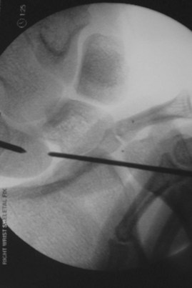
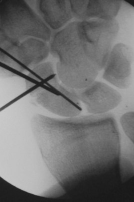
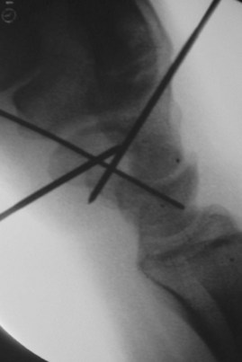
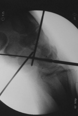
 If you plan on placing just one screw, the goal is to have the wire perfectly centered down the axis of the scaphoid on both views (Figs. 68-11 and 68-12).
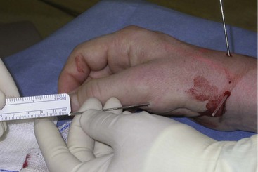
 With the guidewire tip just in subchondral bone, measure the interosseous length by placing another guidewire of equal length parallel to it at the entry point (either distal or proximal) and measuring the difference (Fig. 68-13). The headless screw should be 3 to 5 mm shorter than this measured length to ensure that all of the threads are buried.

Step 4: Reaming
 Before reaming, an antirotation wire should be placed parallel and 3 to 4 mm away from the first. This wire serves both to maintain reduction once the guidewire has been overdrilled and to oppose the rotational forces exerted when twisting in the headless screw.
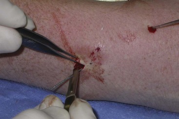
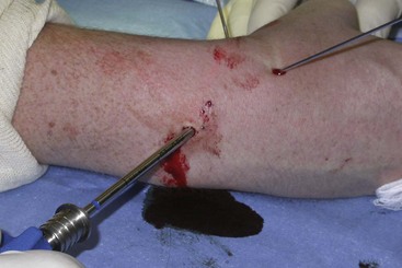
 A 5-mm incision is made at the wire entry site, and blunt dissection is performed down to the capsule to ensure that the extensor tendons are not pierced by the wire (Fig. 68-14).
 By means of a power or hand reamer, carefully ream over the guidewire up to the subchondral bone of the distal fragment (Fig. 68-15).
Step 5: Screw Insertion
 Insert a headless screw under fluoroscopic guidance until it is just short of the distal cortex (Fig. 68-16).
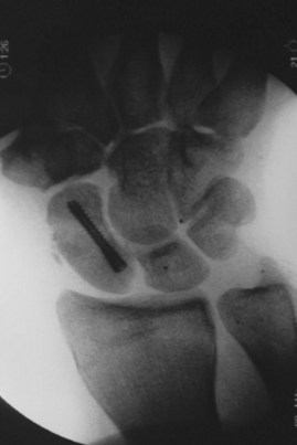
 Remove the guidewires. Verify fluoroscopically that the fracture is well reduced and that the screw is fully contained in the bone (Fig. 68-17).
Step 5 Pearls
We prefer a “mini” headless screw (e.g., Acutrak Mini) over a standard-sized screw because it is more appropriately sized to the dimension of the scaphoid in most patients. Standard-sized screws fill nearly the entire medullary canal and could theoretically inhibit bony fusion.
For more comminuted fractures, it might be advantageous to place two smaller headless screws side by side.
Postoperative Care and Expected Outcomes
 A postoperative volar and dorsal thumb spica splint is removed at the 2-week postoperative visit. This is replaced with a removable Orthoplast thumb spica splint, constructed by the occupational therapist, which is worn at all times until healing is confirmed radiographically.
Bond CD, Shin AY, McBride MT, Dao KD. Percutaneous screw fixation or cast immobilization for nondisplaced scaphoid fractures. J Bone Joint Surg [Am]. 2001;83:483-488.
Dias JJ, Wildin CJ, Bhowal B, Thompson JR. Should acute scaphoid fractures be fixed? A randomized controlled trial. J Bone Joint Surg [Am]. 2005;87:2160-2168.