Procedure 60 Arthrodesis of Finger and Thumb Interphalangeal and Metacarpophalangeal Joints
 See Video 44: Arthrodesis of Thumb Metacarpophalangeal Joint


Examination/Imaging
Clinical Examination
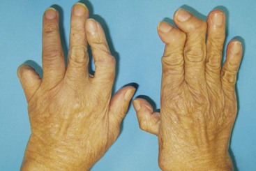
 Angular deformity of the joints. Assess for possible passive correction as an indication of the degree of soft tissue contracture that may restrict surgical correction.
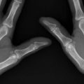
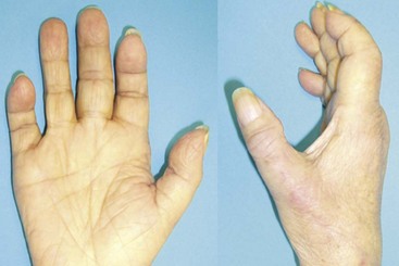
 Instability with subluxation and dislocation of joints (Fig. 60-1)
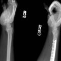
 Rheumatoid arthritis of the hands with unstable carpometacarpal and MCP joints of the right thumb with Z-deformity, subluxation of the left index and small finger proximal interphalangeal (PIP) joints, and deformity of the distal interphalangeal (DIP) joints of the right hand (see Fig. 60-1)
 Swelling and tenderness of the joints from effusion and osteophytes


Imaging
 Obtain standard posteroanterior and lateral radiographs of the involved finger and thumb.
 The alignment and bone stock around the involved joint should be noted (Fig. 60-2).
 Figure 60-2 shows posteroanterior radiographs of the same hands, confirming the clinical findings in Figure 60-1. In addition, there is dislocation of the MCP joint of the left thumb.
Surgical Anatomy
 The cartilage destruction leads to loosening of collateral ligaments and instability of the IP joint. The pinch and grasping stresses lead to angular deformity at the involved joint. Irritation from osteophytes and synovitis leads to pain, joint effusion, and loss of pinch and grasping strength. The extensor tendon, in particular at the DIP joint, may be attenuated, causing mallet deformity, which in chronic cases results in fixed flexion deformity.


Exposures
Metacarpophalangeal Joint


Proximal Interphalangeal Joint
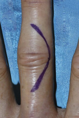
 The PIP joint is exposed through a gentle curve over the joint and extended over the adjacent bones (Fig. 60-3).
 Figure 60-3 shows the dorsal curvilinear incision over the PIP joint.


Distal Interphalangeal Joint
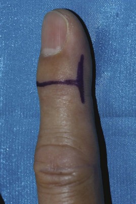
 The DIP joint of the fingers and the IP joint of the thumb are exposed with an H incision, with the transverse part of the H directly over the dorsum of the joint (Fig. 60-4). Alternatively, a Y incision centered over the DIP joint may be used.

 The collateral ligaments on both sides are divided, allowing the joint to be hinged open dorsally.
Pearls
In joints with fixed deformity, release of the soft tissue needs to be performed to reposition and reduce the joint in an optimal position.
The volar plate, especially at the DIP joint, may tent the joint apart, preventing compression of the bones for arthrodesis, and needs to be adequately released.
Procedure
Preparation of Joint Surfaces (Crest and Trough Method)
Step 1
 The joint and its adjacent bone ends are adequately exposed.

 Soft tissue release is done to reduce and realign the joint.
Step 2
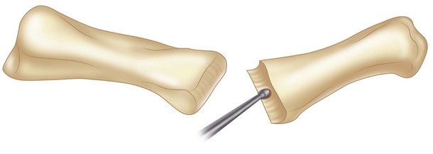
 The bone ends are fashioned with the aim of a “crest-and-trough” fitting.
 Figure 60-5 shows the use of the bur to create the crest-and-trough shape of the joint.
 Fashioning the distal bone end is done using a small bur, following the concave shape of the articular surface (see Fig. 60-5). Running the bur transversely over the articular surface creates a gentle trough. The bone surface is burred evenly until the subchondral bone is reached and all the residual cartilage removed.

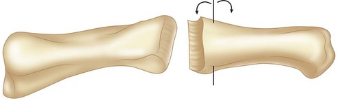
 Trial reduction of the joint is done to ensure a proper surface fitting and axis alignment. Adjust the shape of the bone surfaces in small steps until the surfaces fit well and axis alignment is achieved (Fig. 60-6).
 Figure 60-6 shows that the crest-and-trough configuration of the joint allows fine adjustment of the fusion angle around the axis as shown.
Step 2 Pearls
Fashioning of the bone ends with the crest-and-trough technique requires minimal removal of bones. It allows preservation of much of the subchondral bone and improves the stability of the fixation. This fashioning technique effectively controls the axial alignment and corrects any preexisting deviational deformity. The large area of bone contact that the technique confers is maintained over a wide range of joint flexion.
Alternatively, the bone ends can be cut using a saw, with the distal bone at 0 degrees and the proximal bone at the desired angle of fusion.
Oblique Interfragmentary Screw Fixation Technique
Step 3
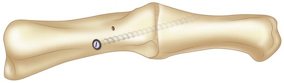
 Fixation of the bone ends is done with an oblique interfragmentary screw, using a 2-mm screw for the PIP joint and the thumb IP joint and a 1.5-mm screw for the DIP joint.
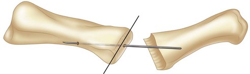
 The proximal drill hole is made over the proximal bone end. The drill hole is set at 45 degrees to the transverse joint surface, using the retrograde drilling technique (Fig. 60-7). The entry point is at “dead center” of the condylar surface for a fusion angle set at 0 degrees. For a joint fusion angle of 10 to 30 degrees of flexion, the entry point is set at 1 to 1.5 mm (the diameter of the drill bit) more palmarly.
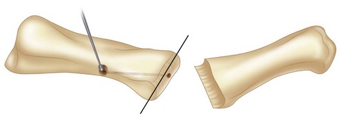
 Countersink the exit point of the drill hole over the proximal shaft, and further recess the proximal cortex of the drill hole with a small bur to ensure proper seating of the screw head (Fig. 60-8).
 Figure 60-8 shows widening of the screw entry point with a bur to accommodate the screw head.
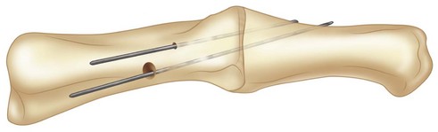
 Reduce the joint, set it to a predetermined angle of fusion, and ensure proper axial alignment and lateral reduction. Temporary pinning of the fusion is done with 0.8-mm K-wire parallel to, but at the same time avoiding encroaching on, the drill hole and intended direction of the screw (Fig. 60-9).
 Figure 60-9 shows a parallel K-wire driven across the joint before drilling.


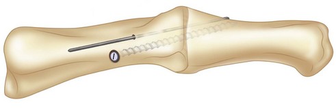
 Fixation is completed with the required interfragmentary screw (Fig. 60-10). Compression across the joint is achieved by precompressing with a small bone clamp before insertion of the screw.

Step 3 Pearls
Temporary pinning of the joint with a 0.8-mm K-wire parallel to the drill hole allows compression of the joint before insertion of the screw.
The joint can be readjusted to the correct angle without refashioning the bone ends, yet maintaining similarly good bone contact through a wide range of fusion angles.
Perform the antegrade drilling of the distal bone end after the correct angle of fusion has been confirmed.
Step 3 Pitfalls
The bone can be displaced when introducing the interfragmentary screw. Counterpressure on the distal bone during screw introduction is always necessary. Remove the temporary K-wire after the fixation is completed.
For fusion of the finger DIP joints and thumb IP joint, aim the screw from proximal to distal and slightly palmarly. This will avoid having the screw tip encroach onto the nail matrix.
Step 4
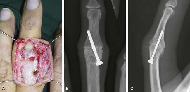
 After completion of the fixation, fluoroscopy is repeated to confirm the final reduction and the screw position and length (Figs. 60-12 and 60-13).
 Figure 60-12A shows the intraoperative appearance of PIP joint fusion; parts B and C show the radiographic appearance of the joint.
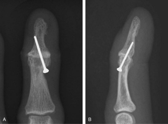
 Figure 60-13A and B shows the radiographic appearance of the DIP joint fusion.
 The extensor tendon is repaired with running 5-0 absorbable suture.

Tension Band Wiring Technique (Parallel Wiring)
Step 1
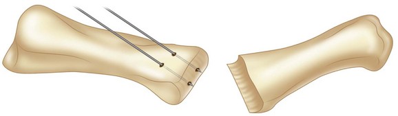
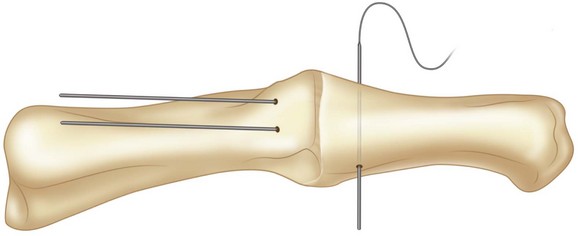
 Two parallel K-wires, sized 1 or 1.25 mm (depending on the size of the bone), are driven retrograde from the joint into the head of the proximal phalanx at an angle equivalent to the desired angle of fusion (Fig. 60-14).

 Figure 60-15 shows two K-wires driven retrograde from the PIP joint into the proximal phalanx in the long axis of the middle phalanx and parallel to each other.
Step 1 Pearls
Appropriately sized K-wires should be used.
Frequent irrigation of the bone should be done during insertion of the K-wires to prevent bone necrosis.
Leaving the K-wires protruding 1 to 2 mm at the fusion surface allows the K-wires to engage into the middle phalanx during positioning before they are driven in.
Step 1 Pitfalls
The angle at which the K-wires are driven into the proximal phalanx should be the fusion angle. Otherwise, either the fusion angle will be wrong, with the middle phalanx having to accommodate the angle of the K-wires, or the K-wire will not be along the length of the middle phalanx, resulting in a less stable fixation.
Step 2
 The middle phalanx is apposed and adjusted to the desired angle of fusion, and the K-wires are driven into the shaft of the middle phalanx.
 The placement of the K-wires is then checked with the mini C-arm to ensure that the tips are not impinging into the distal phalanx or the flexor tendons (see Fig. 60-15).
Step 2 Pitfalls
Care must be taken to ensure that the K-wires are not too long because they may splint the DIP joint or, if driven through the volar cortex, skewer the flexor tendons.
Figure 60-15 shows parallel K-wires driven across the PIP joint from the proximal phalanx into the shaft of the middle phalanx of the small finger under radiographic control.
Step 3
 The hub of an 18- or 19-gauge needle is removed and the needle is used as a cannulated drill to drive a pilot hole transversely across the base of the middle phalanx, about 1 cm from the PIP joint (Fig. 60-16).
 Figure 60-16 shows a 19-gauge needle used to drive a hole in the coronal plane of the middle phalanx about 1 to 1.5 cm from the PIP joint.

 The K-wires are then bent and cut short, and the tips are twisted down against the bone to avoid soft tissue irritation (Fig. 60-17).

Step 3 Pearls
Ensure that the cerclage wire is tightened evenly on both sides of the PIP joint around the K-wires.
The bent part of the K-wire should be turned toward the bone. This lessens soft tissue irritation as well as helping to hold the wire better.
The knot of the cerclage wire should be put at the side of the PIP joint to lessen soft tissue irritation.
Figure 60-17 shows the cerclage wire tightened around the K-wires, which are then bent to hold the cerclage wire and prevent irritation of soft tissues.

Tension Band Wiring Technique (Cross Wiring)
Step 1
 The joint is positioned at the angle of fusion, and a 1- or 1.25-mm K-wire (depending on the size of the bone) is inserted obliquely to hold the position of the joint.
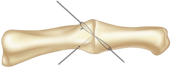
 Once the position of the joint (flexion angle and rotational alignment) is confirmed, a 24-gauge cerclage wire is used as a figure-of-eight tension band across the joint around the two ends of the oblique wire. It is tightened to achieve adequate tension and compression across the joint (Fig. 60-18).
 Figure 60-18 shows tension band wiring applied over the first K-wire before driving in the second K-wire.
Step 2
 The alignment of the joint is checked again before another K-wire is inserted obliquely on the opposite side in a crossed fashion.


Step 2 Pearls
The position of the cross K-wires should be in the midaxial plane. This will ensure that the tension band effect is applied appropriately across the arthrodesis site.
The second K-wire could be driven first into the proximal bone without penetrating across the joint, then driven through only after tension band wire has been tightened over the first wire.
Step 3
 The K-wires are cut short and bent toward the bone to hold the cerclage wires in place as well as to avoid soft tissue irritation. They may also be cut just short enough to hold the cerclage wires without being bent (Fig. 60-19).
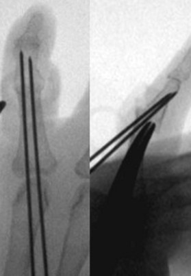
 Figure 60-19 shows the final radiographic appearance of MCP joint fusion using the cross-tension–band wiring technique.

Postoperative Care and Expected Outcomes
 The finger is dressed in a soft bulky supportive dressing to prevent excessive postoperative motion. At the first dressing about 1 week after surgery, the finger is immobilized in a palmar trough splint. Supervised active motion to the proximal joint is allowed after the second week. The splint is worn for 6 weeks or until the radiographs show union, whichever is longer.

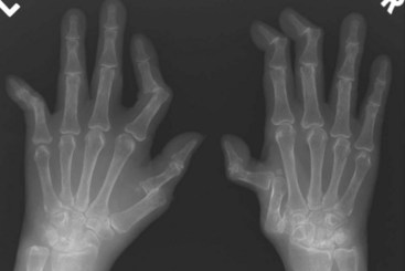
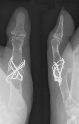
 Function is significantly improved with well-aligned and stable joints (Fig. 60-20).
Pearls
For the tension band wiring technique, active movement converts a distraction force into a compressive force owing to a flexion moment around the pivot point formed by the tension band, thereby promoting joint compression and union.
Figure 60-20 shows the postoperative appearance after fusion of the MCP joint of the right thumb and DIP joint of the index and long fingers. Thumb carpometacarpal joint arthroplasty was also done.
Stern PJ, Gates NT, Jones TB. Tension band arthrodesis of small joints of the hand. J Hand Surg [Am]. 1993;18:194-197.
Teoh LC, Yeo SJ, Singh I. Interphalangeal joint arthrodesis with oblique placement of an AO lag screw. J Hand Surg [Br]. 1994;19:208-211.
Uhl RL. Proximal interphalangeal joint arthrodesis using the tension band technique. J Hand Surg [Am]. 2007;32:914-917.
Uhl RL, Schneider LH. Tension band arthrodesis of finger joints: a retrospective review of 76 consecutive cases. J Hand Surg [Am]. 1992;17:518-522.