Procedure 50 Open Reduction and Internal Fixation of Phalangeal Shaft Comminuted Fractures
Indications
 Displaced unstable fracture with angular and/or rotatory deformity is seen, usually with associated shortening.
 Extensive fracture with long segment of shaft involvement occurs, often with intra-articular extension.
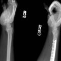
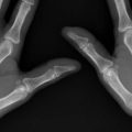
 Fracture comminution in the form of multiple butterfly fragments or multiple cortical splits (Fig. 50-1) is suitable for cerclage-wiring–assisted plate fixation technique.
 Comminution with larger butterfly fragments is suitable for interfragmentary screw and plate fixation technique.
 Associated soft tissue injuries need to be addressed at the same time.
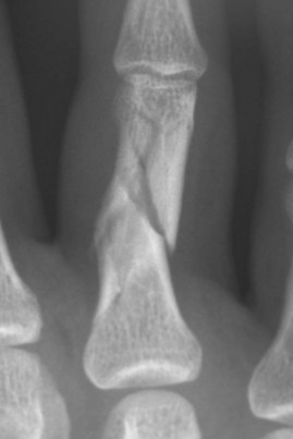
FIGURE 50-1


Surgical Anatomy
 The flexor tendons are held by the A2 pulley to the proximal phalanx with very little free space between the tendon and the bone.
 Fracture fragments with extensor tendon or collateral ligament attachments should be reduced and stabilized to preserve optimal joint function.
 Dorsal approach with splitting of the extensor tendon in the midline provides a wide exposure to the dorsal surface of the proximal phalanx, yet leaves sufficient soft tissue attachments on the palmar aspect to maintain blood supply to the bone fragments.


Exposures
 For the proximal phalanx, the fracture is exposed through a dorsal longitudinal incision, extending from the metacarpophalangeal (MCP) joint to the proximal interphalangeal (PIP) joint if necessary (Fig. 50-2). The extensor tendon is split in the midline.
 For the middle phalanx, exposure is through a dorsal longitudinal incision extending from the PIP joint to the distal interphalangeal (DIP) joint. The triangular ligament is then divided and the lateral bands of the extensor tendon elevated (Fig. 50-3A and B).
 The periosteum is incised and elevated, sufficient to expose the bone fragments and not to denude the bone fragments totally.
 Collateral ligament, extensor tendon, and tendon sheath attachments should be preserved.
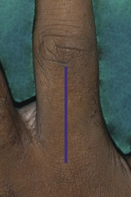
FIGURE 50-2
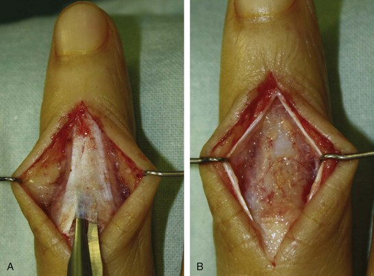
FIGURE 50-3
Pearls
The extensor tendon and the periosteum should be incised together down to the bone surface. Do not separate the periosteum from the extensor tendon. The periosteum is thin and friable, and keeping it with the extensor tendon helps to retain its integrity.
The proximal and distal joints usually need to be opened to ensure adequate access to all the fragments and to ensure articular reduction for intra-articular fractures.
Soft tissue attachments to bone fragments should be preserved to ensure the integrity of joint structures and vascularity of the bone fragments.
Soft tissue attachments to the fragments aid in reduction with traction.
Procedure
 Two techniques are described here. The strategy is to restore the integrity of the cylindrical shape of the shaft to confer stability. The proximal and distal periarticular fragments are then fixed onto this cylindrical construct to obtain overall stability.
Cerclage Wiring–Assisted Plate Fixation Technique
Step 1
 The fracture is adequately exposed, and the major fracture fragments are identified.
 The sites for cerclage wire placement are identified.
 A C-shaped guide for the cerclage wire is fashioned from a 21-gauge hypodermic needle (Fig. 50-4).
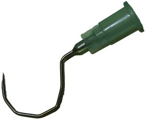
FIGURE 50-4
Step 1 Pearls
The ideal site of cerclage wire placement is at the midpoint of the fracture fragment. A 1-cm long fragment can accommodate a cerclage wire, and fragments longer than 1 cm may accommodate two.
The C-shaped guide is fashioned using a pair of straight mosquito forceps or small needle holders (with about 4-mm-thick jaws). The 21-gauge needle is gripped firmly, but not so hard as to crush it. Beginning at the tip, the forceps is used to bend the needle by about 30 degrees. The needle is progressively bent from the tip to the hub to create a C-shaped contour. About 5 mm from the hub, the needle is bent 90 degrees in the opposite direction to create a handle that will help in introducing the needle below the phalanx. A 28-gauge wire can easily be inserted into the needle tip for a distance of 1 cm.
Step 2
 The C-shaped guide for the cerclage wire is introduced at the predetermined site (Fig. 50-5).
 A 28-gauge stainless-steel wire is threaded through the C-shaped guide. The C-shaped guide is withdrawn, leaving the stainless-steel cerclage wire in position.
 These steps are repeated until all the intended cerclage wires are inserted (Fig. 50-6).
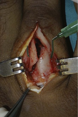
FIGURE 50-5
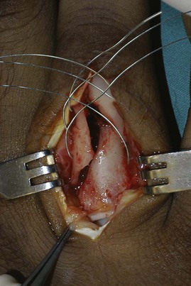
FIGURE 50-6
Step 2 Pearls
Rotate the C-shaped guide for the cerclage wire around the palmar surface of the bone. Do not allow any space because this may enter the flexor tendon.
Passively flex the distal joints of the finger and observe the C-shaped guide for the cerclage wire. If the flexor tendon is impaled, the guide will move.
Step 3
 Reduction of the fracture fragments begins by applying longitudinal traction on the finger distally and maintaining the correct rotation position.
 The reduction is further improved by gentle nudging of the fragments with a periosteal elevator. This is further assisted by gentle compression with a hemostat, straight mosquito forceps, and a small pointed reduction clamp.
 The cerclage wires are tightened one at a time from most proximal to distal. The last bit of reduction is achieved by tightening the tension of the cerclage wires. The cerclage wires provide a preliminary stability of the reduction (Fig. 50-7).
 Fluoroscopy images are obtained to ensure the placement of the cerclage wires. These wires should sit close to the palmar surface of the bone. A gap of 5 mm or more indicates that the cerclage wire has passed palmar to the flexor tendon; this should be removed and reinserted correctly.
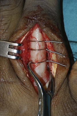
FIGURE 50-7
Step 3 Pearls
Step 4
 Neutralization plating of the fracture with 1.5-mm plate and screws is done (Fig. 50-8).
 The plate should be sufficiently long to bridge the comminution zone and still have two additional holes for fixation at each end of the bone beyond the comminution zone.
 The screw insertion for the plating is on the proximal end first, then the distal end of the bone. Care is taken to ensure that the rotation of the finger is correctly maintained. Additional screw fixation to the comminution zone is possible at the holes where there is no cerclage wire interposing or the presence of fracture line.
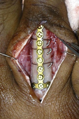
FIGURE 50-8
Step 4 Pearls
Step 5
 After the fixation is completed, fluoroscopy is repeated to confirm the final reduction and to ensure the correct screw placement and length (Fig. 50-9).
 The periosteum is closed with absorbable suture if it is still available. The extensor tendon is also closed with absorbable suture. The skin is closed with interrupted nonabsorbable suture.
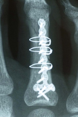
FIGURE 50-9
Interfragmentary Screws and Neutralization Plate Fixation Technique
Step 1
 Starting from proximal to distal, the largest fragments are held together with straight mosquito forceps.
 Often, some of these fragments include the proximal or distal articular fragments, and simultaneous articular reduction must be achieved.
Step 1 Pearls
Traction during surgery aids in reduction of the fragments and uses soft tissue to splint the fragments for fixation.
Straight mosquito forceps with a fine tip are useful for reducing and holding bone fragments while the interfragmentary screws are being inserted, especially for smaller fragments, for which the use of the pointed reduction forceps is not suitable.
Small K-wires may be used to hold some fragments together while other fragments are being reduced.
Step 1 Pitfalls
Step 2
 The fracture fragments are held in reduction with a compressive force before drilling and screw fixation (precompression) (Fig. 50-10).
 The drill hole is made for the screws, using appropriately sized drill bits without overdrilling the proximal cortex, as is done in conventional interfragmentary screw insertion.
 The drill hole is countersunk.
 Small bicortical screws are inserted using screws ranging from 1 to 1.5 mm, depending on the fragment sizes.
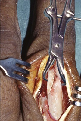
FIGURE 50-10
Step 2 Pearls
Precompression of the fragments with bicortical screw fixation instead of the classic interfragmentary screw fixation technique with overdrilling of the proximal screw hole allows easier screw insertion.
The fragment should be at least the size of three screw diameters.
Countersink the near hole to accommodate the screw head whenever possible.
Ensure that the interfragmentary screws do not catch the collateral ligaments and result in restriction of motion of the involved joint. If passing at the level of the collateral ligaments, longitudinal split of the collateral ligament can be made, and the screw head should be sunk below the ligament to the level of the bone.
Step 2 Pitfalls
Avoid overcompression because this may displace the fracture or even cause fragmentation of the fracture fragments.
The screw length must be exact: if the screw is too short, it does not hold the fragments well; if the screw is too long, there is a risk for impingement of the flexor tendons leading to rupture or stiffness of the finger.
Ensure that the direction of the screw is correct; otherwise, the screw will push away the far cortex instead of holding it in compression, resulting in a loss of reduction.
Avoid overtightening of the screws because this may risk fracture of the fracture fragments.
Step 3
 The next closest fragment is then reduced and held in reduction with straight mosquito forceps and fixed with the appropriately sized interfragmentary screw, using the same technique as in step 2.
 Progressively, each subsequent fragment is built onto the first two fragments until the cylindrical shape of the phalangeal shaft is restored and overall alignment is achieved (Fig. 50-11).
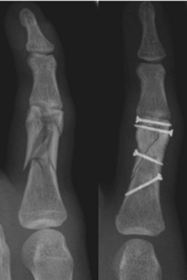
FIGURE 50-11
Step 4


Step 5
 A neutralization plate is applied dorsally to span the proximal-to-distal condylar region (Fig. 50-12).
 A T- or extended H-plate may be used as deemed suitable (Fig. 50-13).
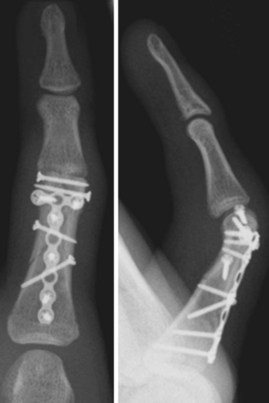
FIGURE 50-12
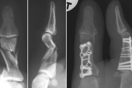
FIGURE 50-13
Step 5 Pearls
Step 5 Pitfalls
Screws with the wrong lengths may not be accessible once the neutralization plate is fixed and hence should be checked and corrected before the plate is applied.
Some implant systems do not have the appropriate-length plate. This should be verified and the appropriate implants made available before surgery.


Postoperative Care and Expected Outcomes
 The dressing is lightened the next day, and active range of motion within the limits of pain is initiated.
 The operated finger is splinted in the safe position with the PIP and DIP joints in full extension for 4 to 6 weeks.
 Interval “out-of-splint” active range of motion for 10 to 15 minutes four to five times a day continues. The active range of motion is assisted with passive ranging as tolerated.
 Sutures are removed at 12 to 14 days.
 Strengthening starts after 4 to 6 weeks with radiologic evidence of bone healing.
Lu WW, Furumachi K, Ip WY, Chow SP. Fixation for comminuted phalangeal fractures: a biomechanical study of five methods. J Hand Surg [Br]. 1996;6:765-767.
The rigidities of five fixation methods in a comminuted phalangeal fracture model were studied: four K-wires, lateral plating with six screws, lateral plating for the triangular butterfly fragment defect with four screws, fixation of butterfly fragment with two screws, and fixation with two crossed intramedullary K-wires. Mechanical testing of compressing, bending, and torsion was performed for each fixation. Lateral plating with six screws provided the most rigid fixation, followed by the four–K-wire technique. (Level IV evidence)
Mitra A, Elahi MM, Spears J, Mitra A. Cerclage clamp: a useful tool in open reduction and internal fixation of complicated metacarpal and phalangeal shaft fractures. Plast Reconstr Surg. 2004;114:169-173.
The authors describe the use of a newly designed bone reduction clamp with a channel to facilitate the passing of cerclage wires around the bone for long oblique and spiral fractures of the metacarpal and phalangeal shaft, supplemented with interfragmentary screws. They have used this instrument successfully in 14 cases, although the results were not reported. (Level V evidence)
Teoh LC, Tan PL, Tan SH, Cheong EC. Cerclage-wiring-assisted fixation of difficult hand fractures. J Hand Surg [Br]. 2006;31:637-642.
The paper described a technique for difficult hand fractures with multiple butterfly fragments, multiple cortical splits, or intra-articular extension. In 17 difficult hand fractures in 16 patients with an average follow-up of 44.5 months, the average total active range of motion was 247 degrees (range, 220 to 260 degrees). (Level V evidence)