Imaging
Radiology and Catheter-Based Angiocardiography
Radiology
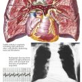
Radiologic examination is an essential part of the evaluation of cardiac disease. The size of the heart and identification of chamber enlargement and pericardial, cardiac, and coronary calcification, as well as information on heart function and hemodynamics, can be determined from chest radiography, fluoroscopic examination, and angiocardiographic observations.
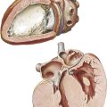
The myocardium, valves, and other heart structures have similar radiodensity and therefore cannot be distinguished radiologically unless calcified. Similarly, the walls of the cardiac chambers cannot be visually separated from the blood within unless the opacity of the blood is increased by the injection of a contrast material. The outer borders of the heart can be seen because the relatively homogeneous cardiac silhouette is contrasted against the lucent, air-containing lungs.
The shadow of the heart seen on standard radiographs or by fluoroscopy is magnified and somewhat distorted. At the target-to-film or screen distances customarily used, the x-ray beam diverges as it passes through the patient. The structures farther from the film are more magnified than those closer. The distortion can be largely eliminated if the x-ray beam is composed of parallel rather than divergent rays. For most purposes, heart size can be adequately estimated from the standard 6-foot chest film by comparing the apparent cardiac size with that of the thorax. Allowances must be made for the degree of inspiration—the higher the diaphragm, the larger the apparent size of the heart—and the age of the patient. An infant’s heart is relatively large compared with the chest, whereas an older patient’s chest is often small in relation to the heart.
Since the heart is a three-dimensional (3D) structure and only two borders are seen in any one view, radiographs need to be secured in several projections to bring the various chambers and great vessels into profile. Plain films of the chest also allow an evaluation of the pulmonary vasculature and the lung changes that may be associated with heart disease. Increased size and tortuosity of the pulmonary arteries and veins usually indicate a left-to-right shunt, whereas decreased prominence of these vessels is associated with a right-to-left shunt. When the pulmonary artery flow is greatly decreased, as in severe tetralogy of Fallot, the vascular pattern in the lungs often is reticular and nondirectional rather than an orderly radiation of vessels from the lung hilum. This indicates the presence of a significant collateral flow through the bronchial arteries.
In congestive failure or obstruction on the left side of the heart, as in mitral stenosis, the pulmonary veins become engorged. If this progresses to pulmonary hypertension, the veins, together with the peripheral pulmonary arteries, become quite small while the central pulmonary arteries dilate and become bulbous.
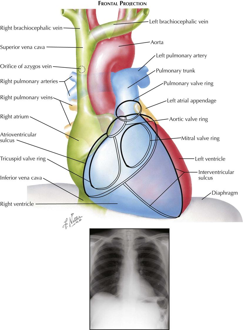
Frontal Projection
Most chest films are made in the frontal projection, so this is the view of the heart usually seen, often providing the first suggestion of cardiac disease. Frontal is the most easily reproducible projection, and thus heart size generally is evaluated in this view (see Plate 3-1). Enlargement of the left atrium and left ventricle, as well as the right atrium, generally can be recognized in the frontal projection. The right ventricle, although it forms no borders, can produce characteristic changes in the cardiac contour.
The upper half of the right contour of the cardiac silhouette is formed by the superior vena cava (SVC) and the lower half by the lateral wall of the right atrium. The margin of the SVC is straight, but that of the right atrium bulges outward. The angle between these two contours represents the superior aspect of the right atrium. If the patient takes a deep inspiration, an indentation on the right border of the heart can be seen just above the diaphragm, identifying the junction of the inferior vena cava (IVC) and right atrium.
On the left side, the uppermost part of the cardiovascular silhouette is formed by the distal arch of the aorta as it curves posteriorly and inferiorly to become the descending thoracic aorta. This is seen as a localized bulge extending from the left side of the mediastinum above the right tracheobronchial angle. This bulge usually produces a localized indentation on the left side of the esophagus. In the presence of a right aortic arch, the bulge will be on the right side and will displace the esophagus to the left. Immediately below the aortic bulge, the main pulmonary trunk and left main pulmonary artery are border forming. A small segment of the left cardiac silhouette below the pulmonary artery is formed by the left atrial appendage. This segment normally is flat or slightly convex and is continuous with the curve of the left ventricle, which forms the largest part of the left border of the cardiac contour. The point of transition between the normal left atrial appendage and the left ventricle usually cannot be identified on radiographs.
The apex of the heart is formed by the left ventricle. In the frontal projection the right ventricle is completely hidden within the cardiac silhouette. Occasionally on deep inspiration, a part of the diaphragmatic surface of the heart near the cardiac apex is disclosed. An indentation in this region marks the interventricular sulcus between the two ventricles.
Enlargement of the right atrium causes outward bowing and increased curvature of the border of the right side of the heart. When the right ventricle increases in size, the heart enlarges to the left, the apex is usually lifted, and the groove of the interventricular sulcus appears higher on the apex of the heart than normal. As it enlarges, the right ventricle elongates as well as widens, resulting in elevation of the main pulmonary artery. As the left ventricle enlarges, the cardiac apex is displaced downward and to the left. Often the entire left cardiac border is displaced to the left, becoming increasingly convex.
Left atrial enlargement is detected in the frontal view primarily by dilatation of the left atrial appendage, which produces a localized bulge of the left contour below the pulmonary artery segment. In addition, the enlarged left atrium often increases the density of the central part of the cardiac silhouette and, when sufficiently large, may elevate the left main bronchus. With increasing dilatation, the right border of the left atrium may be seen within the cardiac silhouette to the right of the spine, producing a second curved contour medial to the right atrial margin. With further enlargement, the left atrium may project behind and beyond the right atrium so that the left atrium will form the right border of the cardiac shadow. The border of the right atrium will then be seen within the shadow of the left atrium.
Calcification of the cardiac valves is most often caused by rheumatic valvulitis, calcific aortic stenosis, or bacterial endocarditis and involves the mitral and aortic valves. In the frontal projection the mitral valve lies to the left of the spine, and as the heart beats, calcifications on this valve will describe a flat, elliptical trajectory extending downward and to the left. The aortic valve is usually projected over the left side of the spine and moves in a relatively straight line upward and slightly to the right. Because of the overlapping shadows of the vertebral bodies, small calcific deposits on the aortic valve may be difficult to detect in the frontal view but are readily seen in the lateral projection. The pulmonic (pulmonary) valve is projected to the left of the spine, higher than the aortic and mitral valves, and moves vertically with the cardiac pulsation. The tricuspid valve lies over the spine and moves in a horizontal plane.
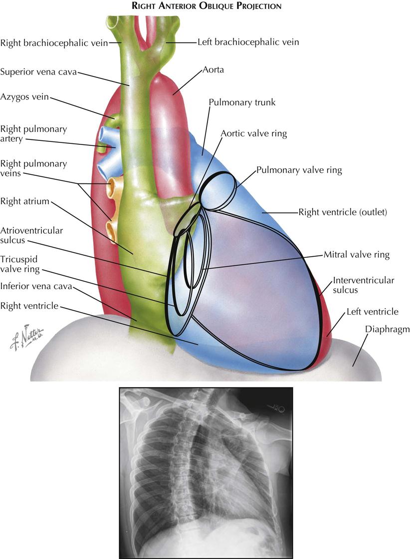
Right Anterior Oblique Projection
The right anterior oblique (RAO) view is used mainly to evaluate left atrial enlargement and abnormalities of the right ventricular outflow (outlet) tract (see Plate 3-2). RAO is also the best projection in which to study calcification of the mitral valve. During selective left ventricular angiocardiography, the RAO view is used to evaluate mitral stenosis or insufficiency, because the mitral valve is seen tangentially, and the left atrium is projected entirely behind the left ventricle. RAO is the only view in which these two chambers do not overlap.
In a properly positioned RAO view, the shadow of the spine lies to the left of the cardiac silhouette, and a thin vertical band of air-containing lung separates the two structures. The aortic arch is foreshortened in this view, and the descending aorta partially overlaps the vertebral column.
The right border of the heart is formed by the right posterior aspect of the left atrium above and the posterior border of the right atrium below. As the obliquity of the projection is increased, more of the left atrium comes into profile.
The uppermost part of the left border of the cardiovascular silhouette is almost vertical and represents the ascending aorta. Just below this segment, the cardiac contour slopes downward and to the left in a gentle curve and is formed by the outflow tract (outlet) of the right ventricle and pulmonary trunk. The inferior continuation of this curve is formed by the anterior wall of the left ventricle. As in the frontal view, the body of the right ventricle is in contact with the diaphragm and cannot be visualized.
The mitral valve is seen almost tangentially and is projected over the midpart of the cardiac silhouette. Because confusing overlapping shadows are absent and the direction of mitral valve motion is perpendicular to the x-ray beam, calcification of the mitral valve is best detected fluoroscopically in RAO projection. The elliptical orbit of the valve is mainly directed horizontally. The aortic valve is thrown clear of the spine, and although in contact with the upper border of the mitral valve, calcification of the aortic valve can be recognized as it moves mostly in an up-and-down direction. This projection also provides the greatest separation of the aortic and pulmonic valves. The pulmonary valve lies at a level higher than the aortic valve and to its left, touching the left border of the cardiac silhouette. The line of motion of the pulmonic valve is directed upward and to the right. The tricuspid valve is seen almost tangentially and slightly behind the mitral valve. The tricuspid valve moves horizontally with the cardiac pulsation, and in the rare case of tricuspid calcification, the valve is easily mistaken for a calcified mitral valve.
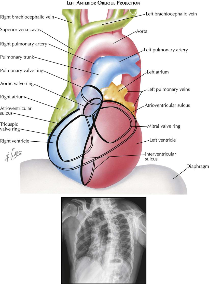
Left Anterior Oblique Projection
Although no longer used for plain chest radiographs, the left anterior oblique (LAO) view is useful in evaluating the size of the left atrium and left ventricle during angiography (see Plate 3-3). The aortic arch is seen clearly because it is oriented approximately parallel to the film and is projected with minimal foreshortening. A selective left ventricular angiocardiogram in the left oblique projection is useful in the detection of a ventricular septal defect, because most of the muscular interventricular septum and a part of the membranous septum are seen tangentially.
The right border of the cardiac contour is formed by the right atrium above and the right ventricle below. As the degree of obliquity is increased, more of the right ventricle becomes border forming. Enlargement of the right atrium increases the convexity of the upper right cardiac border, whereas enlargement of the right ventricle usually results in a more generalized increase in curvature of the upper right border.
The left cardiac contour is formed mostly by the left ventricle, except for the upper quarter, which is contributed by the left posterior aspect of the left atrium, directly beneath the left main bronchus. Usually, in a proper 45-degree oblique view, the shadow of a normal left ventricle will not extend to the left of the shadow of the spine; extension of this shadow indicates an enlarged left ventricle. However, this sign must be evaluated cautiously because with lesser degrees of obliquity, or if the film is not made in full inspiration, a normal left ventricle may not clear the spine. If the stomach is distended with air, the diaphragmatic surface of the left ventricle can also be evaluated.
The left atrial part of the cardiac contour is usually straight or minimally convex. An outward bulging in this region denotes left atrial enlargement, probably its most sensitive radiographic sign. The esophagus is projected directly over the left atrial segment; therefore barium must not be given until after the LAO film has been made, because significant degrees of left atrial enlargement could be obscured. With greater degrees of enlargement, the dilated left atrium will push the left main bronchus upward and horizontally. The dilated atrium will also encroach on the clear space below the aortic arch.
The greatest length of the aortic arch is seen in the LAO view, and the origins of the great vessels are maximally separated. Thus, LAO is the best projection for identifying aneurysms of the aortic arch and for opacification studies of the aorta and great vessels.
The mitral valve is seen almost directly en face. As a result, calcific deposits on the cusps may be difficult to see because these move on an axis perpendicular to the fluoroscopic screen, with minimal horizontal excursion. In addition, the mitral valve may be hidden partially by the shadow of the spine. Calcification of the tricuspid valve can be differentiated from that of the mitral valve by the complete separation of the two valves in the LAO projection, with the tricuspid valve lying in the right half of the cardiac silhouette. The LAO view is well suited for identifying calcification of the aortic valve, which lies in the upper part of the cardiac silhouette, clear of the spine, and moves along an axis directed upward and to the right. The pulmonic valve is situated slightly higher than the aortic valve and moves upward and toward the left.
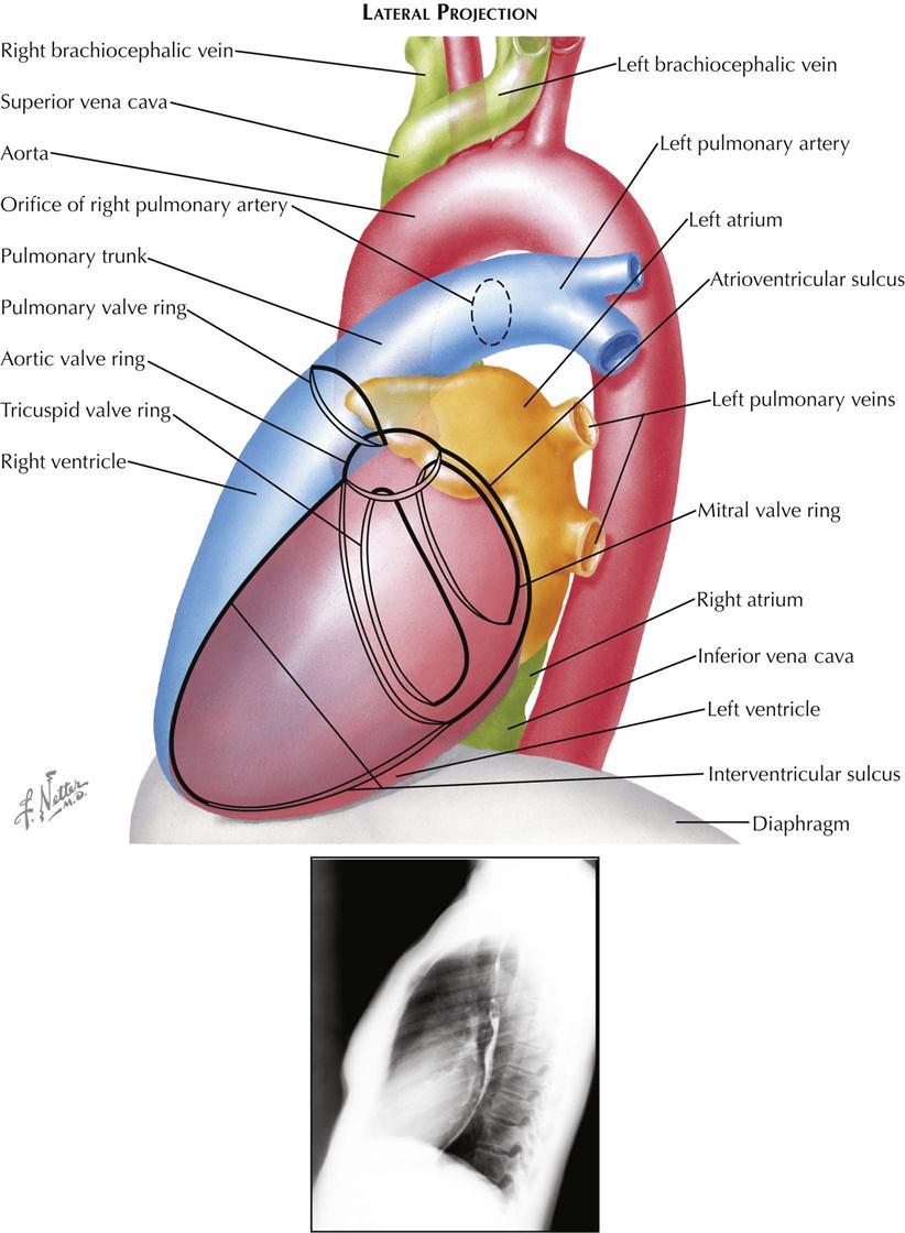
Lateral Projection
In plain radiographs the lateral view is used primarily for evaluating the presence of right ventricular (RV) enlargement, left atrial enlargement, and combined enlargement of the left atrium and left ventricle. Lateral is also the best view for distinguishing between calcification of the aortic and mitral valves. A selective RV angiocardiogram in the lateral projection provides the best visualization of the outflow part of the right ventricle and the pulmonic valve (see Plate 3-4).
In the lateral view the heart is projected clear of the confusing shadows of the sternum and spine. The anterior margin of the cardiac silhouette is formed by the apex and the RV outflow tract. Normally, this abuts on the lower quarter or third of the anterior chest wall. The upper two thirds of the anterior cardiac contour is formed by two convex arcs, slanting upward and posteriorly. The lower, more oblique arc is formed by the RV outflow tract, and the upper arc is formed by the ascending aorta. The radiolucent lung is interposed between these two arcs and the sternum. As it enlarges, the right ventricle bulges forward and progressively obliterates the retrosternal space. Similarly, dilatation and tortuosity, or an aneurysm of the ascending aorta, will encroach on the upper retrosternal space. The upper margin of the aortic arch distal to the origin of the great vessels can usually be identified in the lateral view.
The posterior border of the heart is formed mostly by the posterior wall of the left atrium. Just above the diaphragm, small parts of the right atrium and IVC come into profile. When enlarged, however, the left ventricle may extend farther posteriorly than the right atrium, forming the lower part of the posterior heart border as well. The esophagus lies immediately behind the left atrium and left ventricle, and an enlargement of these chambers will indent the anterior wall of the esophagus and displace it posteriorly. If only the left atrium is enlarged, the indentation on the esophagus is localized at the level of the upper half of the cardiac silhouette; the lower part of the esophagus is in its normal position. When the left ventricle is enlarged as well, it also pushes the esophagus posteriorly, and the backward curve of the displaced esophagus is then continuous over the entire length of the cardiac silhouette to the diaphragm.
Identifying localization of a calcific deposit in the mitral or aortic valve may be difficult. This problem can be resolved in the lateral view. If a line is drawn from the anterior costophrenic sulcus to the point of bifurcation of the trachea, the aortic valve will lie above and in front of this line, whereas the mitral valve will be below and posterior. The mitral valve moves more or less horizontally in the lateral view, and the aortic valve moves on a vertical axis that is tilted slightly anteriorly and upward. The pulmonic valve is located above the aortic valve and more anteriorly, extending to the anterior border of the cardiac shadow.
Angiocardiography
Chest radiography and fluoroscopy demonstrate only the outer borders of the heart and great vessels. Considerably more information is obtained when the blood is opacified by introducing a radiopaque contrast medium into the vascular system to visualize the inner borders of the cardiac chambers and vessels during catheter-based angiography. The structure and motion of the cardiac valves can be studied, as well as cardiac and pulmonary hemodynamics.
The basic requirements for successful catheter-based angiocardiography are (1) rapid injection of the radiopaque contrast material so that it flows as a bolus and (2) cineangiography of the heart to follow the course of the contrast material. The iodinated contrast medium can be injected into a peripheral vein, where it is carried to the heart through the SVC or IVC, or it can be injected through a catheter directly into a specific cardiac chamber, great vessel, or coronary artery. The latter technique, selective angiocardiography, provides greater anatomic detail because the contrast material reaches the chamber as a denser, more compact bolus and is not diluted in the right atrium by nonopaque blood.
A catheter can be placed in the right atrium, right ventricle, or pulmonary trunk by introducing the catheter into a peripheral vein and then advancing it through the SVC or IVC. In children the left atrium can usually be entered by manipulating a catheter in the right atrium, across the foramen ovale. In adults a similar route is used; the atrial septum is punctured by a transseptal needle and a catheter advanced over the needle into the left atrium. The left ventricle is reached by inserting a catheter into a peripheral artery and passing it retrograde through the aortic valve into the ventricle. If the catheter has the proper curve, it can be manipulated backward through the mitral valve into the left atrium. The left ventricle can also be reached by a transseptal catheter passed from the right atrium into the left atrium and advanced through the mitral valve. The left ventricle can be punctured directly through the anterior chest wall, however, and angiocardiography by this route carries substantial risk and is no longer used.
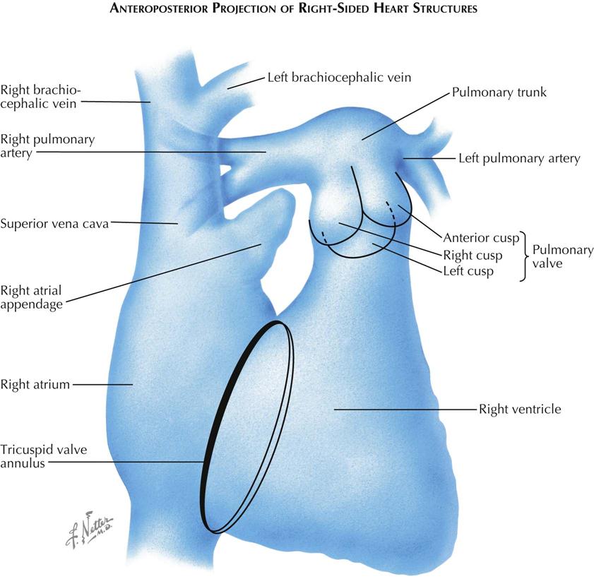
Frontal Projection of Right Side of Heart
The right side of the heart usually can be well visualized by venous angiocardiography as well as selective injection (see Plate 3-5). In the frontal, or anteroposterior (AP), projection the SVC and IVC lie in a straight line to the right of the spine, entering opposite ends of the right atrium. The free wall of the right atrium is thin and is represented by the space between the right border of the contrast-filled atrium and the right border of the cardiac silhouette. Normally, this space is 2 to 3 mm in diameter; increased width of this space indicates a pericardial effusion separating the wall of the right atrium from the pericardium.
The right atrial appendage extends medially and upward from the upper part of the right atrium. The tricuspid valve lies in an oblique plane relative to the AP projection, and the line of attachment of its cusps is often seen as an ellipse overlying the spine. The inferior margin of the tricuspid annulus lies adjacent to the entrance of the IVC into the right atrium. The opening of the coronary sinus lies in the same region. The clinicians must keep this in mind when catheterizing the right ventricle, because a catheter that has entered the coronary sinus and has advanced into the great cardiac vein will follow almost the identical course in the frontal projection as a catheter that has crossed the tricuspid valve and lies within the RV outflow tract. The left border of the tricuspid valve ring forms the left border of the atrium and corresponds to the posterior margin of the tricuspid valve. The right ventricle is in front of the atrium and extends to the right (or anterior) border of the tricuspid valve. Therefore, within the elliptical projection of the tricuspid valve, the atrium and ventricle overlie each other.
The right ventricle is a triangular-shaped chamber that can be divided into two parts: a large, trabeculated inflow part and a smooth, narrow outflow tract. In the frontal view these two parts can be separated by a line drawn from the uppermost margin of the tricuspid valve downward and to the left, toward the apex of the ventricle. This line approximates the course of the septal and moderator bands. The RV inflow tract lies below the line, and the RV outflow tract lies above the line, extending to the pulmonic valve. The right border of the inflow part is formed by the tricuspid valve and the left border by the interventricular septum. The diaphragmatic RV surface is a free wall. The right border of the RV outflow tract is also a free wall, formed by a sheet of muscle extending from tricuspid to pulmonic valve and lying in front of the aortic root. A localized prominence in this sheet of muscle, the crista supraventricularis, is projected en face in this view and cannot be identified. The line of attachment of the tricuspid valve can often be seen during diastole on a selective RV angiocardiogram, because contrast material is trapped between the open valve cusps and the walls of the ventricle, while the orifice of the valve is filled by nonopaque blood entering from the atrium.
The pulmonic valve is projected partially en face and is not well visualized in the frontal view. The pulmonary trunk is usually seen well, but its root may be obscured in part by the RV outflow tract. The right pulmonary artery courses almost directly to the right, and its greatest length can be seen in the AP projection, whereas the left pulmonary artery is directed posteriorly and is foreshortened. A steep LAO or left lateral view is best for the study of the left pulmonary artery. On a venous angiocardiogram, a part of the right pulmonary artery is often obscured by contrast material in the SVC or right atrium, especially if this chamber is enlarged.
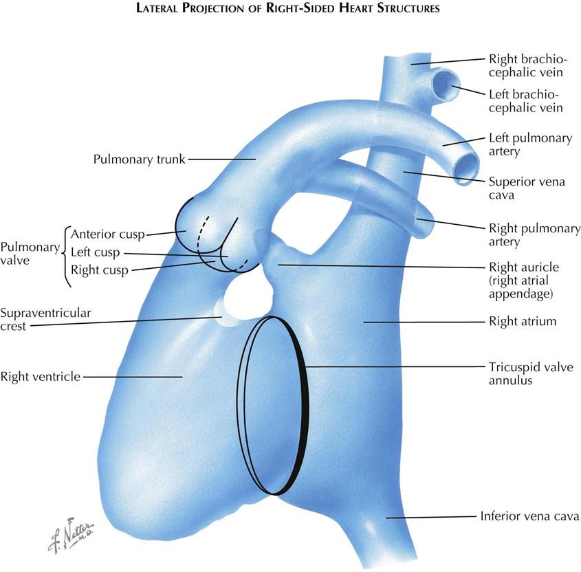
Lateral Projection of Right Side of Heart
In the lateral view the right atrium is projected almost entirely behind the right ventricle (see Plate 3-6). The posterior border of the atrium is a free wall. The interatrial septum lies in an oblique plane and cannot be visualized in either the frontal or the lateral projection. The septum is seen tangentially only in a steep right posterior oblique view. The anterior margin of the right atrium is formed by the tricuspid valve. The atrial appendage arises at a level higher than the valve and extends anteriorly and superiorly. The appendage is triangular shaped, its base continuous with the atrial cavity. The border of the atrial appendage cavity is irregular because of the pectinate muscles.
The ostium of the coronary sinus lies in the inferior part of the atrium just in front of the entrance of the IVC, and the great cardiac vein extends along the posterior aspect of the heart. Therefore a catheter passed through the SVC that has entered the great cardiac vein will curve posteriorly in the lateral view rather than anteriorly, as occurs when the catheter traverses the tricuspid valve to enter the right ventricle.
The right ventricle is best studied by selective angiocardiography because in the lateral view the opacified right atrial appendage, especially if large, often extends far enough anteriorly to obscure part of the RV outflow tract or the pulmonic valve. On a selective study the tricuspid valve can usually be identified as an oblique ring on the posterior aspect of the ventricle. The anterior border of this ring corresponds to the right margin of the tricuspid valve. The main body of the right ventricle, the inflow part, lies directly in front of the tricuspid valve. Just above the upper level of the tricuspid valve, the ventricle becomes narrowed because of the intrusion of a soft tissue mass on the posterior aspect. This represents the crista supraventricularis and marks the level of the entrance to the infundibulum, the RV outflow tract. The anterior border of the RV cavity forms a continuous curve to the pulmonary valve.
The pulmonic valve and its cusps are easily identified in the lateral view, which is an ideal projection for the study of pulmonic valvular stenosis. The lateral view not only can show the limitation in the opening of the valve cusps, but also allows study of the infundibular region and evaluation of associated infundibular stenosis. The pulmonary trunk courses upward and backward, continuing the curve of the anterior RV wall. The left pulmonary artery is well seen in the lateral view because it courses posteriorly, whereas the right pulmonary artery is foreshortened.
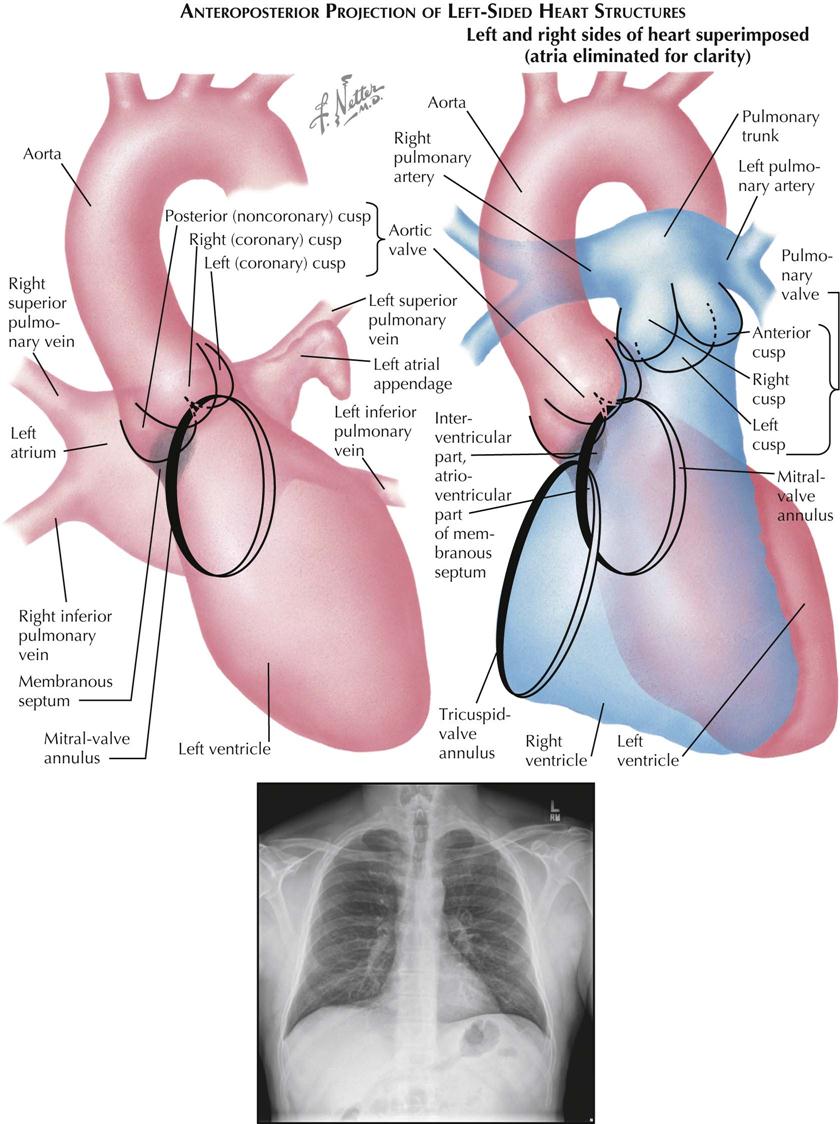
Frontal Projection of Left Side of Heart
The left atrium lies partly above and to the right of the left ventricle (see Plate 3-7). The upper border of the atrial cavity in the frontal (AP) view is straight, slanting upward and to the left. The lower margin is bowed downward. The part of the lower atrial margin that crosses the left ventricular (LV) chamber is formed by the inferior margin of the mitral valve. The two superior pulmonary veins enter the uppermost part of the atrium, and the inferior pulmonary veins enter at a slightly lower level. The left atrial appendage often has a hooklike contour in the AP view, extends to the left border of the heart and overlies the left superior pulmonary vein. It may be difficult to distinguish fluoroscopically whether a catheter in the left atrium has entered the atrial appendage or the left superior pulmonary vein. This can be resolved by viewing the patient in an oblique or lateral projection, because the pulmonary vein extends posteriorly while the appendage lies anteriorly, or by injecting a small quantity of contrast material and outlining the structure.
The left ventricle differs basically from the right ventricle in that the inflow (mitral) valve and the outflow (aortic) valve lie adjacent to each other. Indeed, the anterior cusp of the mitral valve arises from a common annulus with part of the aortic valve. The LV body lies below the two valves, rather than interposed as in the right ventricle. The left ventricle is oval shaped, with its apex pointing downward and to the left. The trabeculation of the LV body is finer than the RV trabeculation. On a selective LV injection the inferior part of the mitral valve ring can usually be identified as a curvilinear interface between the contrast material trapped under the posterior mitral cusp and the nonopaque blood entering from the left atrium above. The superior margin of the mitral ring is continuous with the aortic ring and usually is not well seen in the frontal view. During ventricular systole, the mitral cusps bulge toward the left atrium, the valve orifice is obscured by the contrast material in the ventricle, and the line of attachment of the cusps can no longer be observed. Fingerlike indentations arising from the left and right margins of the ventricle are often seen during systole intruding into the ventricular lumen, representing the papillary muscles.
The location of the membranous part of the interventricular septum can be determined in relation to the aortic valve by ventriculography. It lies beneath the anterior part of the posterior (noncoronary) cusp and a small part of the adjacent right (coronary) cusp and the commissure between the two. In the AP projection the right cusp is seen en face, the left cusp forms the left border of the aortic valve, and the noncoronary cusp forms the right border. The membranous septum thus forms a segment of the right LV border immediately beneath the aortic valve.
The right coronary artery arises from the midpart of the aortic valve in the AP view and extends slightly to the right and downward, running in the sulcus between the right atrium and ventricle. The left coronary artery originates from the left border of the aortic valve. The anterior descending branch courses downward in the interventricular sulcus overlying the left part of the left ventricle. The circumflex branch curves to the right, paralleling the inferior attachment of the mitral valve as it runs in the sulcus between the left atrium and ventricle on the posterior aspect of the heart.
The relationships of the structures on the right and left sides of the heart can be appreciated when the drawings of the two ventricles and their great vessels are superimposed. The ventricles, for the most part, are projected on top of one another. The RV outflow tract is directed upward and toward the left, whereas blood in the left ventricle reaches the aorta by passing upward and to the right. Thus the outflow tracts cross each other, the left passing behind the right. Almost the entire right border of the left ventricle is formed by the interventricular septum, with the uppermost part membranous and the remainder muscular. In addition, a segment of the upper left LV border also represents the interventricular septum. This is the basal part of the muscular septum, which lies in the lower part of the infundibulum just above the septal band on the right side. The uppermost margin of the tricuspid valve attachment reaches almost to the aortic valve, and the origin of the septal cusp of the tricuspid valve actually crosses the membranous septum. Thus the membranous septum on the left side lies completely within the left ventricle, whereas on the right side the anterior part lies in the right ventricle (interventricular septum), and the posterior part lies behind the tricuspid valve in the right atrium (atrioventricular septum).
The upper outflow tract of the right ventricle lies above the left ventricle at the level of the aortic sinuses of Valsalva. The pulmonic valve is at a level higher than the aortic valve, and the two valves touch only near the commissures between right and left cusps.
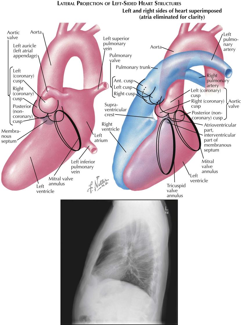
Lateral Projection of Left Side of Heart
In the lateral view the left atrium is projected almost completely behind the left ventricle (see Plate 3-8). The anteroinferior margin of the atrium is formed by the mitral valve. The left atrial appendage (auricle) arises somewhat above the mitral valve and extends anteriorly, crossing the aorta just above the sinuses of Valsalva. If the atrial appendage is sufficiently large, its tip may overlie the pulmonic valve. The posterior border of the atrial cavity is formed by the free wall of the atrium, and the pulmonary veins enter its upper and middle parts.
On a selective LV angiocardiogram the line of insertion of the mitral cusps can usually be seen during diastole as an opaque ring surrounding the radiolucent blood within the valve orifice. The mitral valve forms the posterior boundary of the ventricle. The upper margin of the mitral valve reaches the aortic valve in the region of the commissure between the left (coronary) and posterior (noncoronary) cusps. The LV body extends forward and downward from the mitral valve. The posteroinferior border of the LV body is formed by the free ventricular wall, and the entire anterior border is bounded by the interventricular septum. The papillary muscles may sometimes be seen as radiolucent defects arising from the midpart of the lower border of the ventricle and directed toward the mitral valve.
In the lateral view the right coronary cusp of the aortic valve is seen tangentially, forming the valve’s anterior border. The left and posterior cusps are projected obliquely and lie posteriorly, with the posterior (noncoronary) cusp always the lower of the two. The membranous part of the interventricular septum directly below the commissure between right and noncoronary cusps is not border forming. The superior part of the muscular septum is directly in front of the membranous septum and forms the anterior subvalvular border of the left ventricle.
The right coronary artery arises from the upper part of the right sinus of Valsalva and courses anteriorly a short distance before curving almost directly downward. The main trunk of the left coronary artery is parallel to the x-ray beam and is foreshortened in this view. Its circumflex branch parallels the posterior aspect of the mitral ring. The left anterior or descending branch extends anteriorly and downward, overlying the aortic root, then courses over the right sinus of Valsalva slightly below the origin of the right coronary artery and crosses this artery, so that the lower part of the anterior descending branch is the most anterior of the major coronary vessels. When the right ventricle is enlarged, the sulcus between the ventricle and the right atrium is displaced anteriorly. The right coronary artery lies within this sulcus and in the lateral view is seen completely in front of the left anterior descending branch. In this way, RV enlargement can be recognized on a selective LV angiocardiogram.
When lateral views of the right and left ventricles are superimposed, the tricuspid valve lies anterior to the mitral valve. The upper margin of the tricuspid valve marks the anterior extent of the atrioventricular septum, and the mitral valve marks the posterior extent. The interventricular portion of the membranous septum lies anterior to the insertion of the tricuspid valve. The supraventricular crest is directly in front of the right sinus of Valsalva, and most of the RV outflow tract thus is at a higher level than the left ventricle. Actually, a small part of the LV outflow tract immediately below the commissure between right and left aortic cusps does reach the same level as the subpulmonic region of the right ventricle. The RV and LV outflow tracts are separated in this area by the ventricular septum, and a defect in this region will produce a subpulmonic ventricular septal defect.
Catheter-Based Coronary Angiography
Until recently, diagnosis of human coronary atherosclerosis depended primarily on the physician’s ability to interpret the significance of chest pain described by patients who experience infinitely variable subjective responses to stress. Objective confirmation hinged on the recognition of transient or persistent electrocardiographic changes, which usually indicate the presence of myocardial ischemia, necrosis, or scar tissue replacement of functioning myocardium. Therefore the presence of coronary atherosclerosis could be recognized in a patient only after the disease process had progressed to a point where arterial obstructions were so severe as to cause transient or permanent secondary changes in the myocardium (ischemia or infarction).
Selective cine coronary arteriography provides a clinically useful approach to the precise demonstration of the morphologic characteristics of the lumen of the human coronary artery when used in combination with intravascular ultrasound (see Plate 3-11). In the study of more than 10,500 patients representing all phases of the natural history of coronary atherosclerosis, only nine deaths have been attributable to this arteriographic procedure.
Technique
Sones Technique
With the patient under local anesthesia, the right brachial artery is usually mobilized in the right antecubital fossa immediately above its bifurcation. After heparinizing the distal brachial artery and occluding flow, an 8-French woven catheter 80 cm long, with a special tip that tapers to a 5-French diameter in its distal 2 inches (5 cm), is passed retrograde from the right brachial artery directly into the ascending aorta. The catheter tip is introduced directly into one coronary orifice and then the other under direct vision, using an image intensifier equipped with a closed-circuit television unit to provide direct visualization during the procedure. Pressure measurements from the catheter tip are recorded constantly to permit immediate recognition of arterial occlusion by the catheter tip. The electrocardiogram also is monitored constantly.
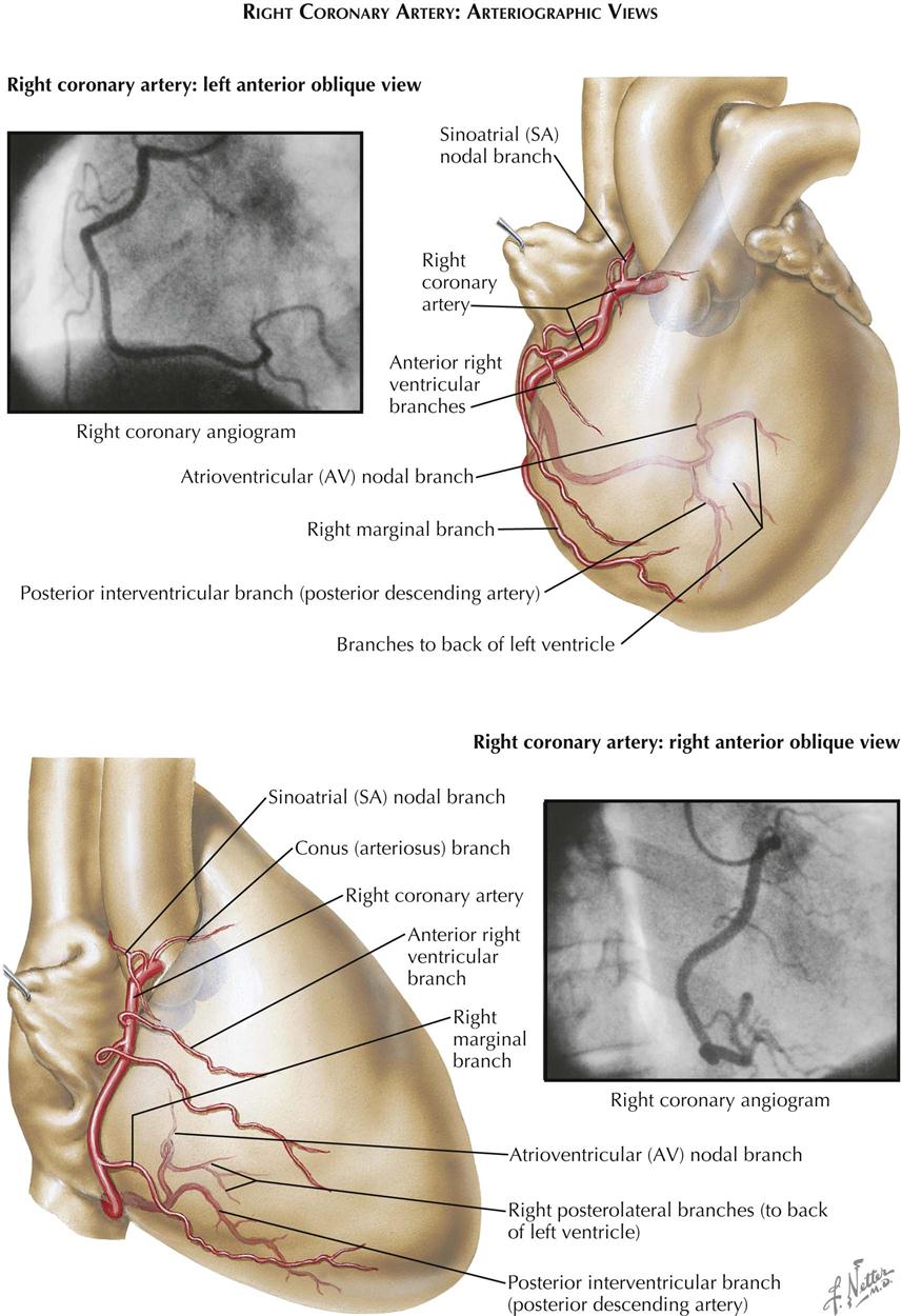
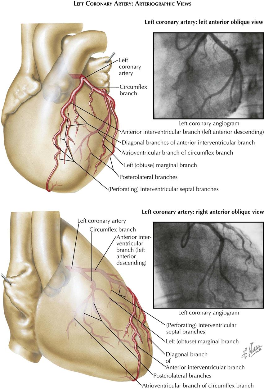
Multiple small doses of radiopaque contrast are injected directly into the orifice of each coronary artery, with the patient positioned in varying right and left anterior oblique projections. Individual projections for each patient are selected based on direct fluoroscopic visualization, to photograph all segments of each vessel in a plane perpendicular to that of the x-ray beam. Usually, four to six arteriograms of each artery are made, in varying RAO and LAO projections. On average, 4 to 6 mL of radiopaque contrast material is injected manually with a 10-mL syringe for adequate opacification of individual coronary vessels. Positioning the heart in multiple RAO and LAO projections is facilitated greatly by the use of a movable camera. The passage of the contrast medium through all branches of the coronary artery is digitally recorded (see Plates 3-9 and 3-10).
After each coronary artery has been opacified effectively in the appropriate projections, the catheter tip is passed across the aortic valve into the left ventricle. Pressure measurements are recorded in the left ventricle. The LV cavity then is opacified selectively with 20 to 30 mL of radiopaque contrast. Left ventriculography is performed routinely in the RAO projection, clearly showing localized LV aneurysms or areas of impaired contractility in the ventricular myocardium caused by interstitial scar tissue replacement or grossly impaired myocardial perfusion. Left ventriculography also permits the ready identification of associated mitral or aortic valve lesions or severely impaired LV function caused by generalized preexisting myocardial injury. The LAO ventriculogram visualizes the ventricular septum and lateral LV wall.
On completion of the procedure, the catheter is withdrawn and the brachial arteriotomy closed by direct suture.
The Sones technique is rarely used now in catheterization laboratories.
Judkins Technique
In contrast to the Sones technique, the Judkins technique is done percutaneously with preformed catheters from the femoral artery. Three catheters are required to perform ventriculography and right and left coronary injections. Ventriculography is usually performed with a “pigtail” catheter before selective coronary angiography. As with the Sones technique, multiple projections are used to identify coronary stenoses. Other catheters (e.g., multipurpose, Amplatz) are introduced percutaneously and often are used if the coronary arteries cannot be engaged by the Judkins catheters.
Radial Artery Technique
Small catheters can be used percutaneously for diagnostic coronary angiography, as well as percutaneous coronary intervention (PCI), if blood flow to the hand is adequate in the radial and ulnar arteries.
Clinical Applications
Coronary angiography can demonstrate distal vessels of the coronary artery as small as 100 to 200 microns in lumen diameter. Segmental variations in lumen diameter of the major branches caused by atherosclerosis result in up to a 10% reduction in diameter (minimal irregularities). More advanced stenotic lesions can limit myocardial perfusion and are visualized easily. Selective opacification of the vessels allows precise delineation of the presence, sites of origin and distribution of effective intercoronary collateral channels, which compensate for severe stenotic or occlusive lesions. In patients with angiographically normal vessels, coronary atherosclerosis may still be present, but myocardial ischemia caused by epicardial vessel stenosis can be ruled out.
Coronary arteriography is essential in selecting patients with coronary atherosclerosis who may benefit from revascularization procedures to improve myocardial perfusion, as well as objectively assessing results. Severe localized obstructions in major proximal arteries are now removed by direct angioplasty/stent or coronary artery bypass. More diffuse obstructive lesions provide an objective basis for planning optimal medical therapy.
After angioplasty or stent placement or postoperatively, repeated coronary arteriograms and selective conduit angiograms permit long-term assessment of the effectiveness of such revascularization procedures, as well as the evolving disease process in the individual patient.
Intravascular Ultrasound
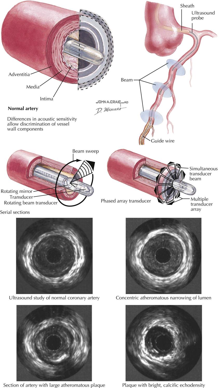
Intravascular ultrasound (IVUS) uses high-frequency sound waves to acquire 3D images to determine the extent and composition of the atherosclerotic lesions in the coronary vessels. IVUS is an invasive technique used in the catheterization laboratory to complement catheter-based coronary angiography and thus requires cardiac catheterization.
A small wire with an echocardiographic transducer at the tip is passed into the coronary artery by way of the cardiac catheter (see Plate 3-11). High-frequency sound waves produce pictures of the arterial wall and any pathology seen in the wall, such as a clot, cholesterol, calcium, or disruption of the endothelium. Both IVUS and angiography can evaluate the length and severity of stenosis, but IVUS adds assessment of the vascular wall, including plaque morphology and cross-sectional area of the stenosis and layers of the vessel wall. IVUS is useful for clinical decision making on whether a patient needs an intracoronary interventional procedure when catheter-based assessment of stenotic severity is equivocal.
Intravenous ultrasound combined with angiography and fractional flow and coronary flow reserve provides a complete assessment of the anatomy and physiology of the blood vessel. The cardiologist uses this information in management of the patient, including effectiveness of aggressive cholesterol lowering and assessment of proper stent deployment after angioplasty.
Transthoracic Cardiac Ultrasound
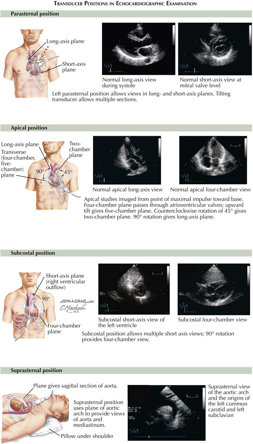
Understanding cardiac ultrasound (US) requires knowing cardiac anatomy and physiology. In addition, performing echocardiography requires considerable experience to develop the necessary technical skills. Cardiac US records reflected sound waves from blood tissue interfaces within the heart and great vessels, thus visualizing the complex cardiac anatomy and providing a remarkably detailed image of heart motion and structure during all phases of the cardiac cycle (see Plate 3-12). Transthoracic cardiac US is one of the most useful diagnostic tests available.
The most common echocardiogram is a two-dimensional (2D) image of cardiac anatomy in different planes, similar to angiography. The 2D echocardiogram provides a detailed picture of spatial relations of the cardiac chambers and valves. One weakness is that the image is somewhat difficult to quantitate. A major limitation is too much lung between the transducer and the heart, making it difficult to obtain good images in patients with chronic obstructive pulmonary disease. Parameters that can be measured with US include the following:
1. Ventricular chamber size and wall thickness
3. Mitral valve: motion, valve thickness, prolapse, calcification, vegetations
Doppler Echocardiography
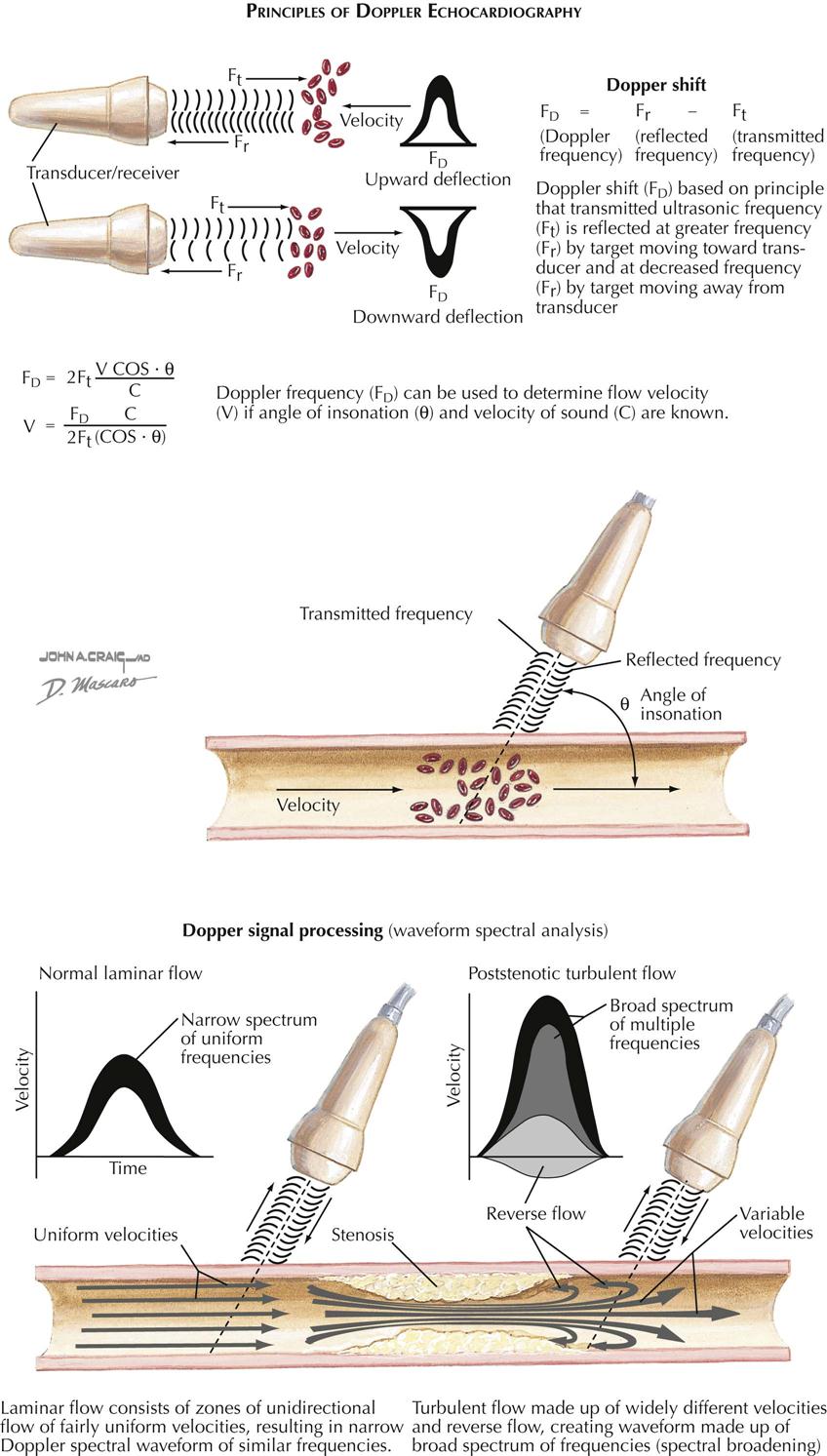
Echocardiography with Doppler ultrasound is based on the principle of estimating velocity and direction of blood flow by using moving red blood cells as a target (see Plate 3-13). There are two types of Doppler US: continuous wave and pulse wave. With the continuous wave technique the transducer can be aimed along the long axis of the ventricle of the aorta and can record all flow patterns encountered. The pulse wave technique allows simultaneous recording of the Doppler and 2D echocardiography. The pulsed technique allows the localization of a Doppler sample in the area of interest (e.g., mitral and aortic valves). Using these Doppler techniques, a transvalvular gradient across the aortic or mitral valves can be derived, as well as estimation of the pressure and severity of mitral, aortic, and tricuspid valve regurgitations.
Doppler color flow imaging techniques allow noninvasive imaging of blood flow through the heart and the display of flow data on the 2D echocardiogram. Color flow imaging can provide the approximate size and direction of any abnormal flow velocity within the heart, including mitral or aortic insufficiency and ventricular septal defect. Doppler echocardiography is extremely sensitive and will detect even the slightest amount of tricuspid regurgitation, even in patients with no evidence of cardiac disease.
The accepted indications of cardiac US include the following:
• Pericardial disease, to evaluate clinical manifestations or suspicion of pericardial disease.
• Cardiac masses, to evaluate patients with suspected cardiac masses.
Transesophageal Echocardiography
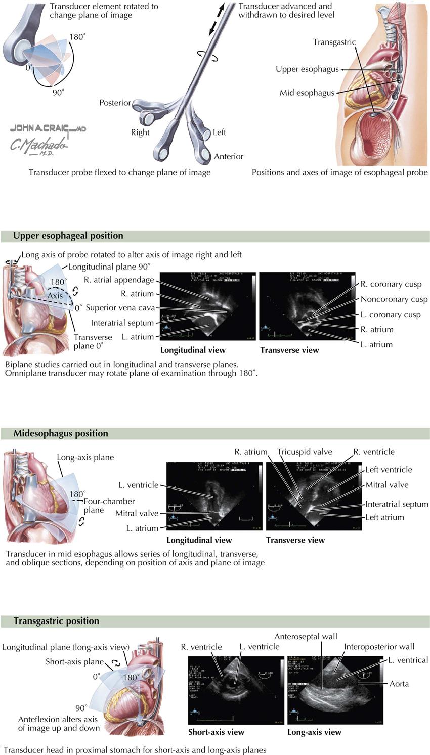
Transesophageal echocardiography (TEE) requires an ultrasound transducer at the tip of a probe that can be passed into the patient’s esophagus, which lies directly behind the left atrium, as well as into the gastric area (see Plate 3-14). Sedation is required, and TEE should be performed only by a certified physician (e.g., cardiologist, cardiac anesthesiologist), not echo technologists. TEE does not replace transthoracic echocardiography but does provide clearer images, especially images that are more difficult to view with transthoracic US, such as the left atrial appendage. This feature is extremely important before cardioversion of patients in atrial fibrillation with uncertain onset. If the atrial appendage is free of clots, the patient is considered at very low risk for emboli to the brain.
The structures evaluated best in adults with TEE are the aorta, pulmonary artery, cardiac valves, both atria and ventricular septum, left atrial appendage, and coronary arteries. However, TEE is rarely used as a diagnostic tool to detect coronary abnormalities in the adult. As with any invasive technique, there is some risk with anesthesia, esophageal perforation, and drug side effects.
In patients undergoing valve surgery, particularly reconstruction (e/g/. mitral valve repair), anesthesiologists trained in TEE provide important information to the surgeon on ventricular function and valve status after repair.
Exercise and Contrast Echocardiography
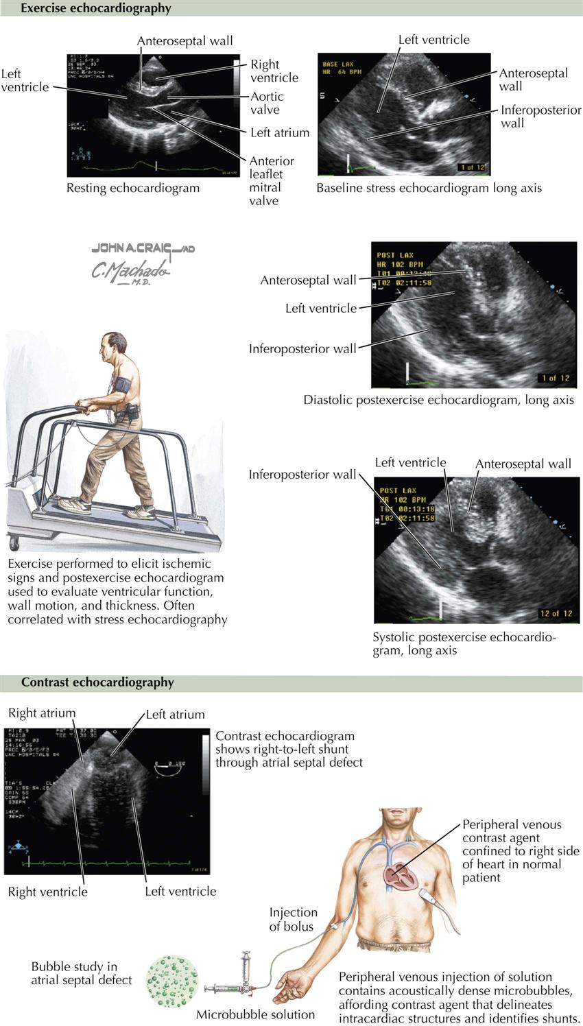
Exercise Echocardiography
This type of stress test generally involves walking on a treadmill after a baseline echocardiogram is obtained (see Plate 3-15). During treadmill exercise the heart rate increases, and if myocardial ischemia occurs, wall motion abnormalities can be detected, which return to baseline at rest or after nitroglycerin. This is highly suggestive of a high-grade stenosis of a coronary artery; identification of the specific artery depends on the distribution of the wall motion abnormality. For example, if the ventricular septum contracts normally at rest but with exercise barely moves, this suggests disease in the anterior descending coronary artery. In contrast, a similar situation with the inferior wall suggests disease of the vessel supplying the posterior descending coronary artery.
If the patient reaches 85% to 90% of predicted maximum heart rate with no transient wall motion changes on the echocardiogram, high-grade coronary stenosis can be excluded in the majority of cases (i.e., excellent negative predictive value).
Contrast Echocardiography
Early attempts at contrast echocardiography involved intravenous injection of agitated saline, which did not cross the pulmonary vascular bed and thus was seen only in the right atrium and right ventricle. Right-to-left shunts could be detected by bubbles in the left atrium or left ventricle. Left-to-right shunts at the atrial or ventricular level could be detected as negative images. Other contrast agents were developed later that allowed passage through the lung after bolus injection in a peripheral vein. These contrast agents consisted of microspheres and were helpful in defining intracardiac structures, demonstrating intracardiac shunts, and enhancing Doppler velocity signals through heart valves. Probably the most important use of these agents is to identify clearly the borders of the left ventricle, which allows an easier and better assessment of left ventricular function than when these agents are not used (see Plate 3-15).
Myocardial Perfusion Imaging
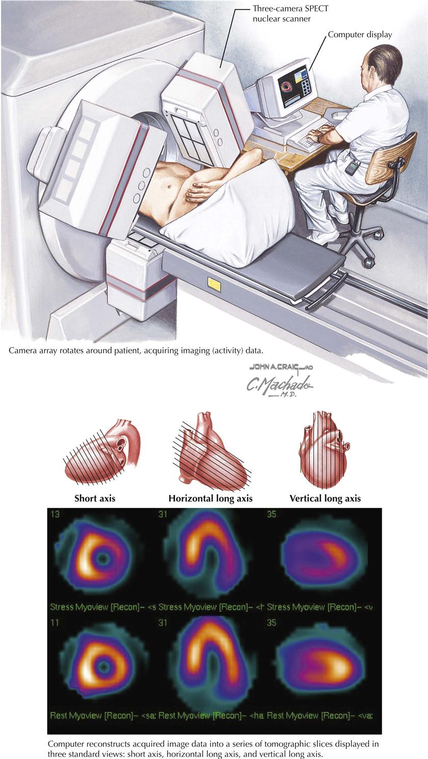
Use of myocardial perfusion imaging (MPI or MPS) is preferable to “stress nuclear imaging,” but both terms are used interchangeably. In general, images at peak stress and at rest reflect changes in the distribution of the radiopharmaceutical if ischemia is present (see Plate 3-16; SPECT, single-photon emission tomography). Indications for MPI are as follows:
Unfortunately, a false-positive test for “ischemia” can occur, especially in patients who have any type of infiltrative disease within the myocardium, such as myocarditis or tumors. False-negative results are also found, especially when the ischemic area of the myocardium is too small to be detected by this technique.
Ventriculography
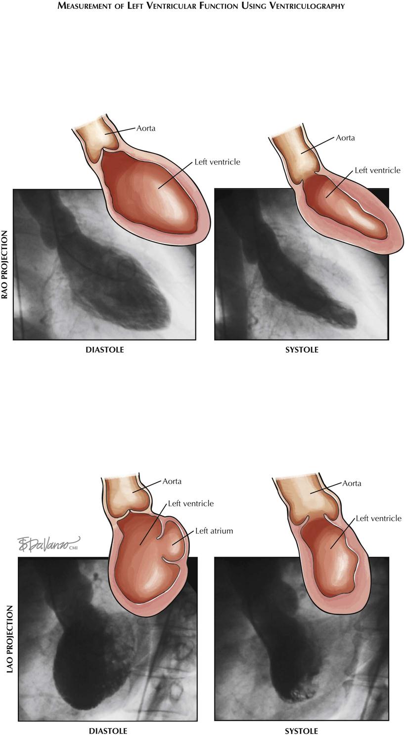
In ventriculography a catheter (usually pigtail) is introduced into the ventricle and radiopaque contrast material injected (see Plate 3-17). The ventricle is then visualized by fluoroscopy/cine as it contracts and relaxes, to assess ventricular wall motion and calculate ejection fraction (EF; normal ≥55%). Ejection fraction is calculated by the formula EF = SV/EDV, where SV is stroke volume and EDV end-diastolic volume.
Hemodynamic study for ischemic heart disease is incomplete without assessment of ventricular function. Catheter-based ventriculography enables identification of areas of akinesis or hypokinesis and allows measurement of global EF if an LAO view is obtained. This information complements coronary angiography; for example, areas of hypokinesis corresponding to the distribution of the coronary arteries with stenotic lesions may provide information that encourages the physician to perform PCI or cardiac surgery to improve contraction of that part of the ventricle.
Ventriculography can be performed in both right (RAO) and left (LAO) anterior oblique projections. In RAO view the anterior, apical, and inferior walls are visualized. In LAO projection the septum, apex, and lateral wall are assessed (see Plate 3-17).
Computed Tomographic Angiography
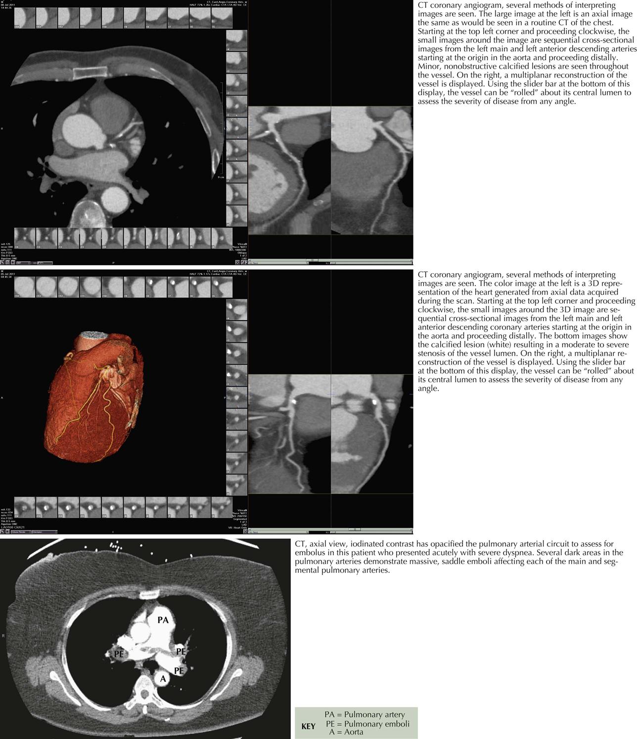
Computed tomographic angiography (CTA) is a 3D image reconstructed from multiple slices of tomographic images of a particular body part (e.g., brain, chest, blood vessels, abdomen, pelvis, joints). CTA of the heart includes the coronary arteries. Because CT studies are created by computer processing, the images can be seen in multiple planes, and ventricles, atria, veins, and arteries can be easily delineated. Pulmonary CTA can reveal emboli in both right and left pulmonary arteries and some subdivisions, as well as in the main pulmonary artery (see Plate 3-19).
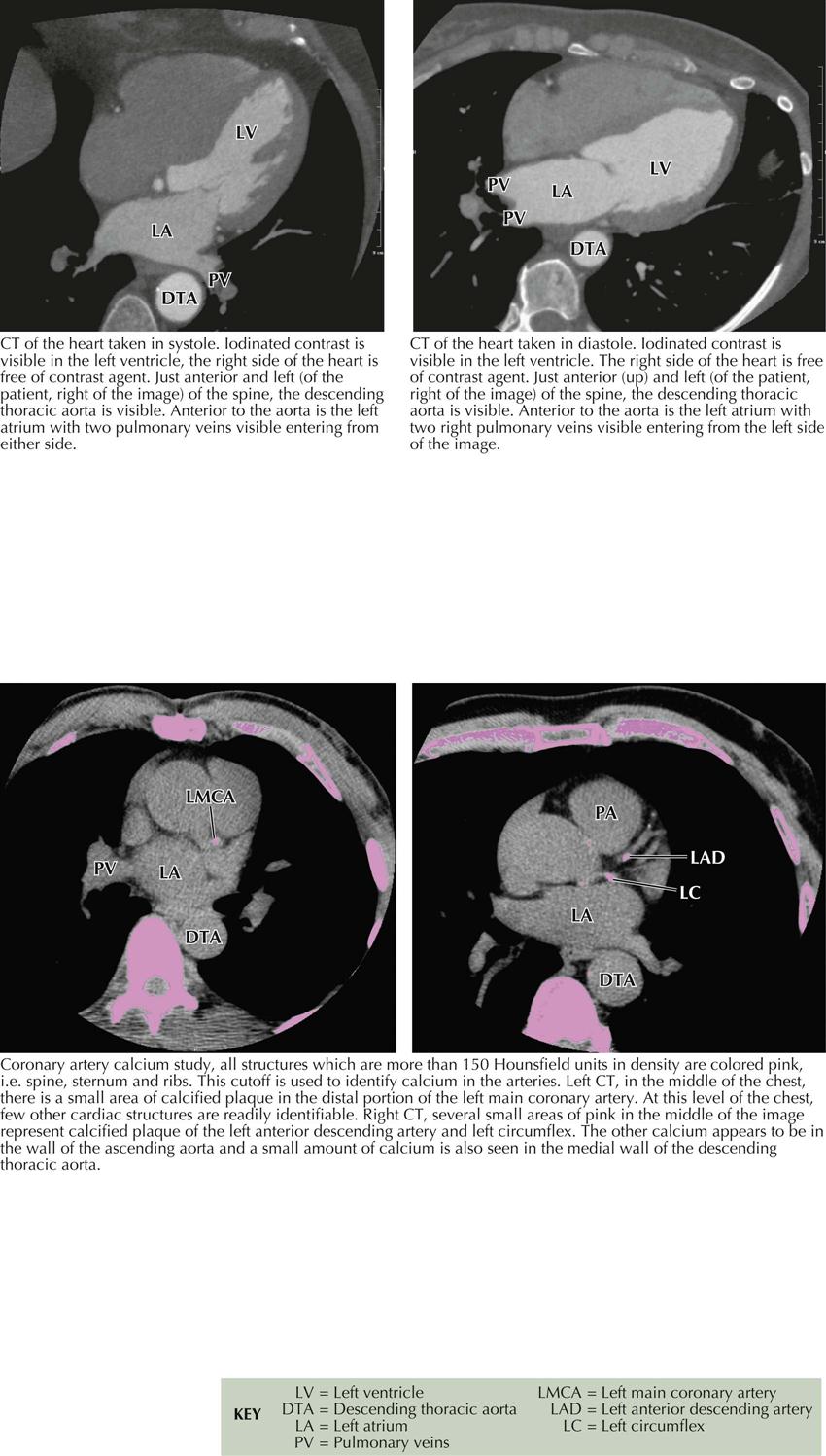
Cardiac Cycle and Calcium Contrast Studies
High resolution and high speed allow imaging of the coronary arteries as well as all chambers of the heart and the great vessels. When imaging the coronary arteries, ionizing radiation is usually confined to diastole, since the majority of blood flow in the coronary arteries occurs during that time in the cardiac cycle (see Plate 3-18). Coronary artery calcium deposits can be quantitated. CTA is especially useful in identifying the course of anomalous coronary arteries (between, posterior/anterior to great vessels).
The radiation dose using CT coronary angiography initially once was quite high, 10 to 15 millisieverts (mSv) per study. The dose is now considerably reduced, particularly when imaging the coronary arteries, which can be imaged in diastole, thus decreasing the amount of radiation exposure as much as 1 to −3 mSv. However, many studies still require greater exposure. Importantly, patients’ exposure to radiation has greatly increased over in the last several years; 49% results from CT-related ionizing radiation, although CT makes up only 12 % of medical radiation procedures. All health care personnel should be aware of patient exposure to radiation.
Because CTA studies require administration of intravenous contrast agents, similar to catheter-based coronary angiography, patient risks include allergic reaction and contrast nephropathy.
Advances and Interpretation
As systems improve, many new clinical CTA investigations will become possible. Computed tomography can help to assess the coronary artery calcium score and evaluate the cardiac chambers and valves, congenital heart disease, aortic and pulmonary disease, and extracardiac structures and abnormalities (see Plate 3-19). Techniques are now being developed to assess not only the anatomic pathology of the coronary arteries but also the physiopathology of a specific lesion that may need a revascularization procedure (i.e., PCI or coronary artery bypass surgery). Preliminary results are encouraging compared with catheter-based coronary angiography and fractional flow reserve, the current reference standard for the physiologic significance of a specific coronary artery stenosis.
Cardiac Magnetic Resonance Imaging
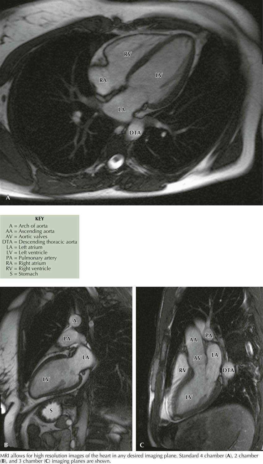
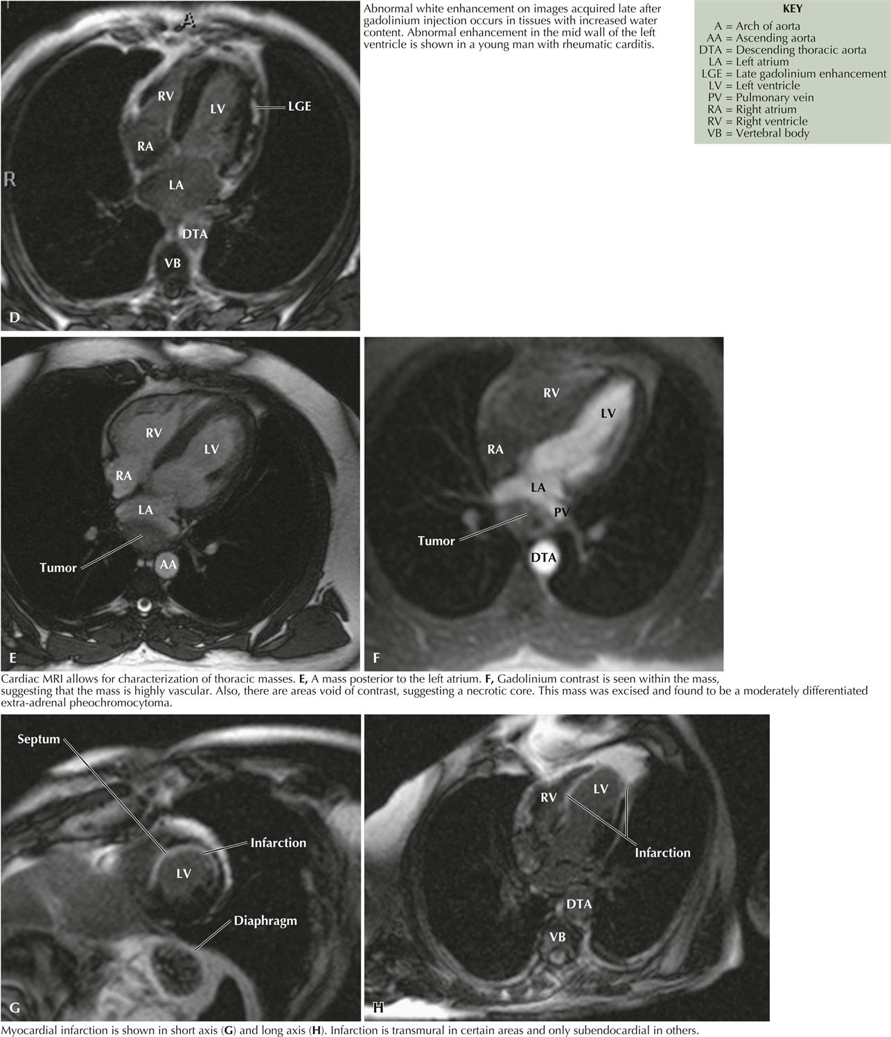
Cardiac magnetic resonance imaging (MRI) does not use radiation and is based on fundamental principles related to the presence of water in all tissues. Since two protons are contained in a water molecule, when put in a magnetic field, they can be aligned. If the magnetic field is turned off, the photons can return to their original position and generate a radio signal that can be detected and quantitated for an image. The images obtained can help assess ventricular function, aortic disease, ischemic heart disease, cardiomyopathies, pericardial disease, valvular heart disease, cardiac masses, congenital heart disease, pulmonary vascular disease, and coronary artery bypass grafting. In the near future, electrophysiologists will be using cardiac MRI to evaluate atrial morphology before atrial fibrillation ablation therapy (see Plates 3-20 and 3-21).
Most cardiac MR images are obtained using gadolinium as a contrast agent. Although gadolinium is generally benign, some patients have developed devastating problems, including nephrogenic systemic fibrosis, a serious occasionally fatal condition.
At this time, most radiologists will not perform cardiac MRI in patients who have implantable devices such as pacemakers or defibrillators. However, some device companies are producing MR-compatible devices, and all devices will probably be MR compatible in the future.