CHAPTER 11 VENTILATOR MANAGEMENT
PRETEST QUESTIONS
1. The following information has been obtained from a ventilator patient.
| Peak inspiratory pressure | 48 cm H2O |
| Plateau pressure | 27 cm H2O |
| VT | 850 mL |
| PEEP | 4 cm H2O |
2. A volume-cycled ventilator is in the control mode and the I:E inspiratory/expiratory ratio alarm is sounding. Which control adjustment would correct this problem?
3. Mechanical ventilation can lead to which of the following complications?
4. Static lung compliance will decrease as a result of which of the following?
5. These data have been collected from a patient whose ventilator was in the control mode.
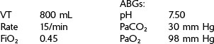
To increase this patient’s PaCO2 to 40 mm Hg, the ventilator rate should be adjusted to what level?
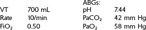
6. The following data have been collected from a patient using a volume ventilator in the control mode.
REVIEW
CRT Exam Content Matrix: IIA6a-b, IIA11a, d, IIID2c, IIID10, IIIF2i6,9, IIIG3f,i,k, l
RRT Exam Content Matrix: IIA2a-b, IIID2c, IIID8, IIIF2e6, IIIG3f,h,k
 Exam Note
 Exam Note
 Exam Note
CRT Exam Content Matrix: IIID2b,d, IIIF2i1-5,11, IIIG3a-e
RRT Exam Content Matrix: IIID2b,d, IIIF2e1,2,3,4,5,9, IIIG3a-e
 Exam Note
106 + [6 × (height in inches − 60 in)]
105 + [5 × (height in inches − 60 in)]

 Exam Note
 Exam Note
 Exam Note
EXAMPLE:
Set VT at 200 mL (0.2 L). Peak pressure reached is 40 cm H2O.
This means that once the patient has started using the ventilator, 5 mL of the set tidal volume will be lost in the tubing for every 1 cm H2O registering on the manometer.
EXAMPLE:
Tubing compliance, 5 mL/cm H2O
Peak inspiratory pressure, 20 cm H2O
Lost volume = tubing compliance × peak inspiratory pressure


 Exam Note
 When the formula for selecting ventilator VT as 10 to 12 mL/kg of body weight is used, this lost volume is taken into account, and this is usually an adequate VT. Some ventilators compensate for volume lost in the tubing by delivering a higher VT automatically.
 Exam Note
EXAMPLE:
Calculate the inspiratory time if the I:E ratio is 1 : 2 and the ventilator rate is 10/min.
 Exam Note
 Exam Note
 Exam Note
 Exam Note
 Exam Note