Periapical radiography
Main indications
The main clinical indications for periapical radiography include:
• Detection of apical infection/inflammation
• Assessment of the periodontal status
• After trauma to the teeth and associated alveolar bone
• Assessment of the presence and position of unerupted teeth
• Assessment of root morphology before extractions
• Preoperative assessment and postoperative appraisal of apical surgery
• Detailed evaluation of apical cysts and other lesions within the alveolar bone
Ideal positioning requirements
The ideal requirements for the position of the image receptor (film packet or digital sensor) and the X-ray beam, relative to a tooth, are shown in Fig. 9.1. They include:
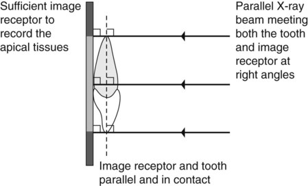
• The tooth under investigation and the image receptor should be in contact or, if not feasible, as close together as possible.
• The tooth and the image receptor should be parallel to one another.
• The image receptor should be positioned with its long axis vertically for incisors and canines, and horizontally for premolars and molars with sufficient receptor beyond the apices to record the apical tissues.
• The X-ray tubehead should be positioned so that the beam meets the tooth and the image receptor at right angles in both the vertical and the horizontal planes.
Radiographic techniques
Paralleling technique
Theory
1. The image receptor is placed in a holder and positioned in the mouth parallel to the long axis of the tooth under investigation.
2. The X-ray tubehead is then aimed at right angles (vertically and horizontally) to both the tooth and the image receptor.
3. By using a film/sensor holder with fixed image receptor and X-ray tubehead positions, the technique is reproducible.
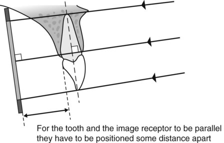
This positioning has the potential to satisfy four of the five ideal requirements mentioned earlier. However, the anatomy of the palate and the shape of the arches mean that the tooth and the image receptor cannot be both parallel and in contact. As shown in Fig. 9.2, the image receptor has to be positioned some distance from the tooth.
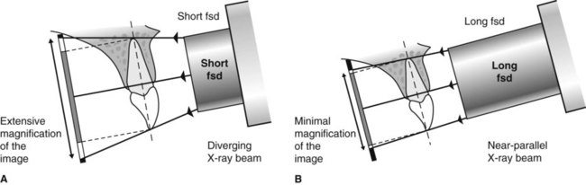
To prevent the magnification of the image that this separation would cause, an X-ray beam as non-divergent as possible is required (see Fig. 9.3). As explained in Chapter 5, this is achieved by having a long focal spot to skin distance (fsd), ideally of 200 mm.
Film packet/sensor holders
A variety of holders has been developed for this technique. The different holders vary in cost and design, but essentially consist of three basic components (as shown in Fig. 9.4):
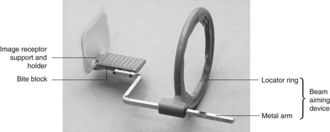
• A mechanism for holding the image receptor parallel to the teeth that also prevents bending of the receptor
• An X-ray beam-aiming device. This may or may not provide additional collimation of the beam.
The different components of the various holders usually need to be assembled together before the holder can be used clinically. The holder design used depends upon whether the tooth under investigation is:
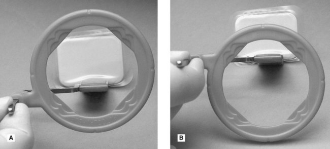
These variables mean that assembling the holder can be confusing, but it must be done correctly. To facilitate this assembly some manufacturers now colour-code the various components. Once assembled correctly the entire image receptor should be visible when viewed through the beam-aiming device, as shown in Fig. 9.5.
The choice of holder is a matter of personal preference and dependent upon the type of image receptor – film packet or digital sensor (solid-state or phosphor plate) – being used. A selection of different holders is shown in Fig. 9.6.

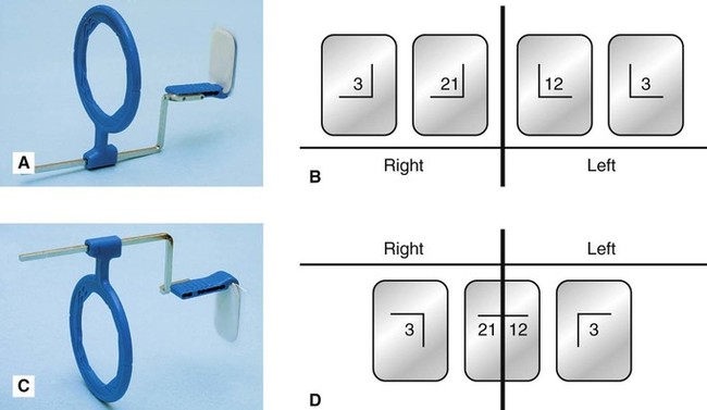
Typically, the same anterior holder can be used for right and left maxillary and mandibular incisors and canines utilizing a small image receptor (22 × 35 mm) with its long axis vertical. Four images in the maxilla and three images in the mandible are usually required to cover the right and left incisors and canines, as shown in Fig. 9.7.
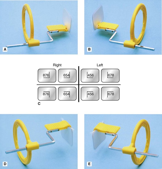
Typically different holders are required for the right and left premolar and molar maxillary and mandibular posterior teeth. The different designs allow the holders to hook around the cheek and corner of the mouth. A large image receptor (31 × 41 mm) is ideally utilized with its long axis horizontal. Two images are usually required to cover the premolar and molar teeth in each quadrant, as shown is Fig. 9.8.
Positioning techniques
The radiographic techniques for the permanent dentition can be summarized as follows:
1. The patient is positioned with the head supported and with the occlusal plane horizontal.
2. The holder and image receptor are placed in the mouth as follows:
a. Maxillary incisors and canines – the image receptor is positioned sufficiently posteriorly to enable its height to be accommodated in the vault of the palate
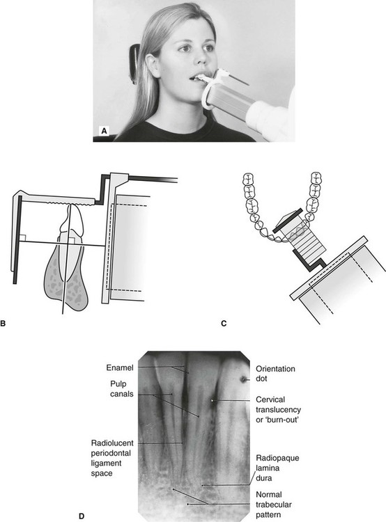
b. Mandibular incisors and canines – the image receptor is positioned in the floor of the mouth, approximately in line with the lower canines or first premolars
c. Maxillary premolars and molars – the image receptor is placed in the midline of the palate, again to accommodate its height in the vault of the palate
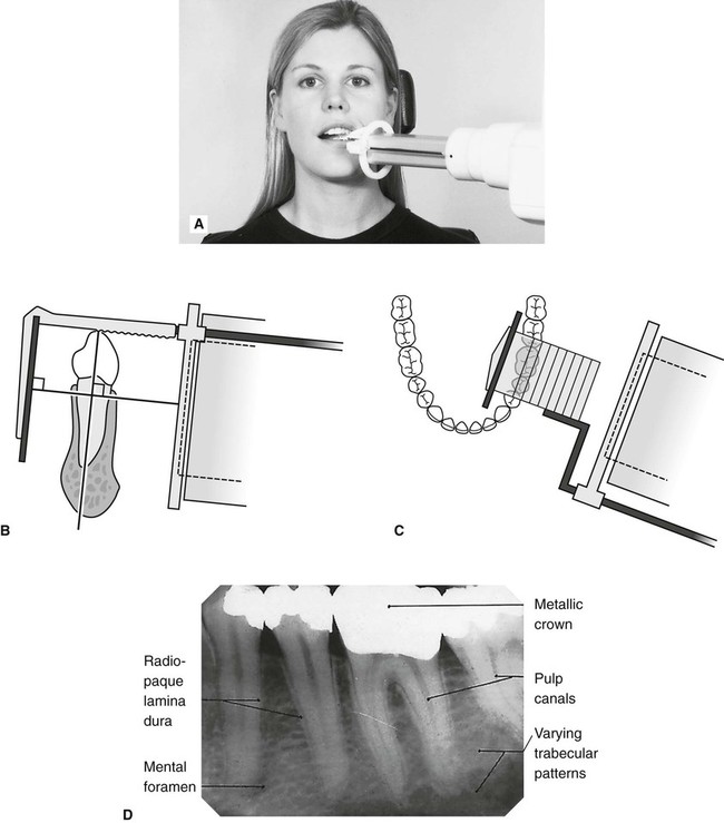
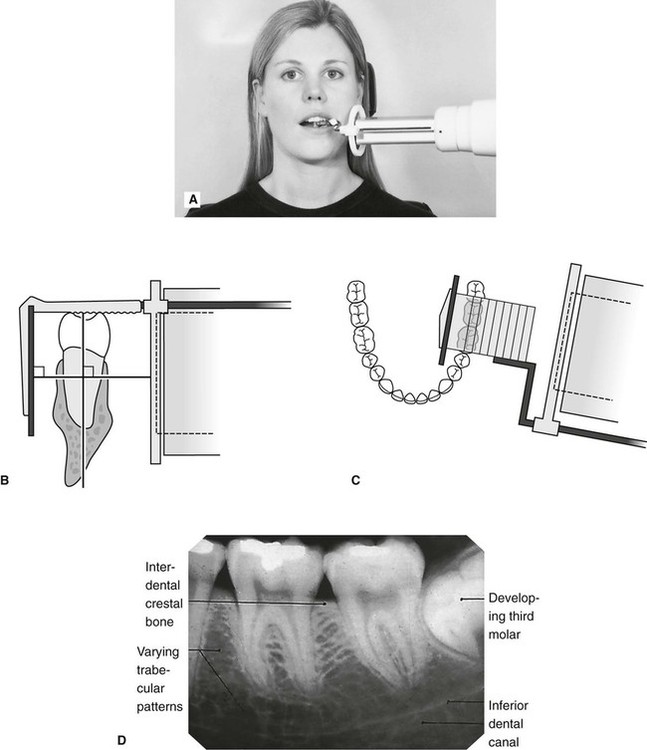
d. Mandibular premolars and molars – the image receptor is placed in the lingual sulcus next to the appropriate teeth.
3. The holder is rotated so that the teeth under investigation are touching the bite block.
4. A cottonwool roll is placed on the reverse side of the bite block. This often helps to keep the tooth and image receptor parallel and may make the holder less uncomfortable.
5. The patient is requested to bite gently together, to stabilize the holder in position.
6. The locator ring is moved down the indicator rod until it is just in contact with the patient’s face. This ensures the correct focal spot to film distance (fsd).
7. The spacer cone is aligned with the locator ring. This automatically sets the vertical and horizontal angles and centres the X-ray beam on the image receptor
Positioning clinically using film packets and digital phosphor plates is shown in Figs 9.9–9.16 for the following different areas of the mouth:
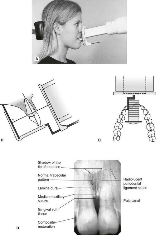
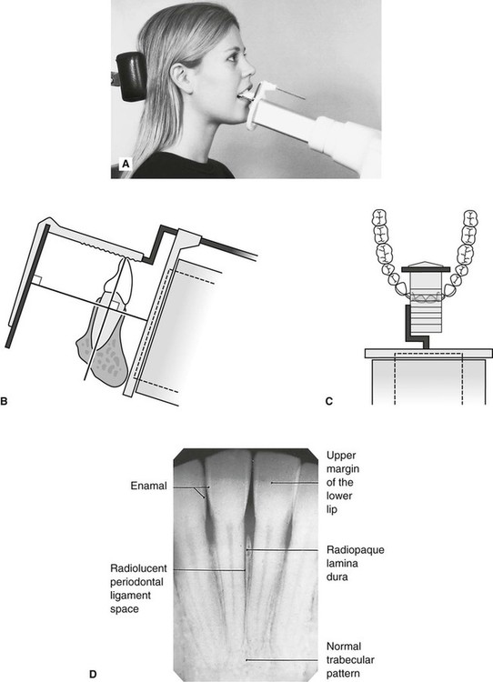
Maxillary central incisor (Fig. 9.9)
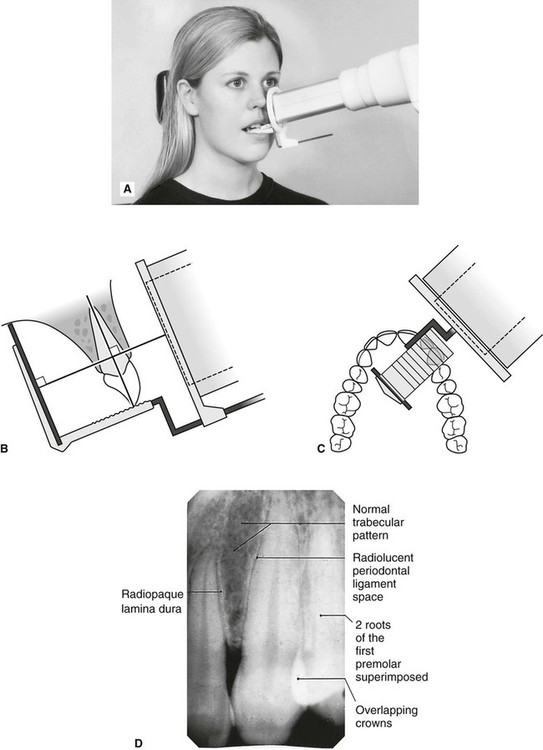
Maxillary premolars (Fig. 9.11)
Mandibular incisors (Fig. 9.13)
1. Full mouth survey is the terminology used to describe the full collection of 15 periapical radiographs (seven anterior and eight posterior) showing the full dentition.
2. When using film packets and digital phosphor plates the end of the receptor with the orientation dot should be placed opposite the crowns of the teeth to avoid subsequent superimposition of the dot over an apex.
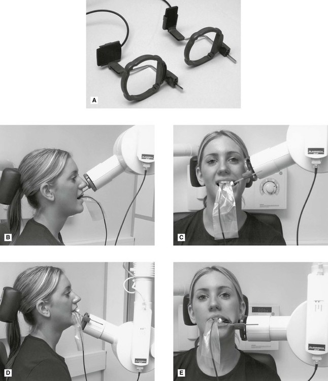
Positioning using solid-state digital sensors
Clinical positioning of holders for the paralleling technique when using solid-state digital sensors can be more difficult because of the bulk and absolute rigidity of the sensor. Those systems employing cables also require extra care with regard to the position of the cable to avoid damaging it. Once the holder is inserted into the mouth, the positioning of the tubehead is the same as described previously when using other types of image receptors and is shown in Fig. 9.17 for different parts of the mouth.
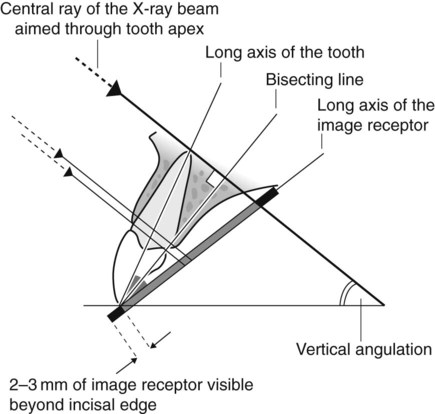
Bisected angle technique
Theory
The theoretical basis of the bisected angle technique is shown in Fig. 9.18 and can be summarized as follows: