Chapter 64 Instrumentation and Stabilization of the Pediatric Spine
Technical Nuances and Age-Specific Considerations
Posterior Spinal Instrumentation in the Pediatric Age Group
Craniocervical Junction (O-C2)
Occipital Screws
Most of the limitations of occipitocervical fixation systems reside in the cranial part of the construct.1,2 The occiput does not easily accommodate instrumentation.2–4 The slope of the occipital bone and the angle it makes with the cervical spine impose unique geometric constraints. These limitations may lead to poor occipital screw purchase, screw loosening, pullout, breakage, and difficulties with screw insertion,5 culminating in catastrophic hardware failure.
Numerous methods of obtaining occipitocervical stabilization have been described, including the use of methylmethacrylate,6 onlay bone graft with wires,7 contoured rods with wires,8 and metal plates with wires or screws.9–11 Internal fixation is advised to guarantee postoperative stability11 and to enhance the rate of arthrodesis.12
In a biomechanical investigation of occipital screw pullout strength, the bicortical pullout strength was found to be 50% greater than unicortical; wire pullout strength was not significantly different from that of unicortical screws,13 although some authors find a posteriorly wired contoured rod less likely to provide a good fusion environment because of less stabilizing potential and greater potential and greater likelihood of loosening with fatigue.14
Although bicortical screw placement may result in superior holding strength secondary to greater cortical purchase,15 caution is needed to avoid overpenetration and potential neurological injury.16 Bicortical occipital screw insertion risks dural laceration, cerebrospinal fluid (CSF) leakage, dural venous sinus injury/thrombosis,17 and subdural/epidural hematoma formation. CSF leakage and sinus bleeding can be stopped with placement of the occipital screws; if a screw cannot be placed, bone wax may be used to plug the drill hole in the bone.
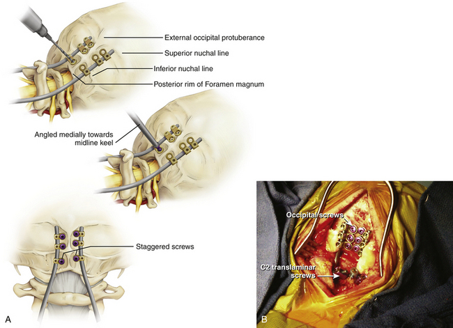
Bicortical screw failure is directly related to screw length, and screw length is dictated by bone thickness.4 Because the occiput is thickest in the region of the midline keel, multiple bicortical fixation points directed towards the midline have been advocated.
The basiocciput below the external occipital protuberance and posterior to the foramen magnum represents the squamous portion and is the site of occipitocervical fusion.2 Screw fixation is more secure in the bone above the inferior nuchal line because bone below this landmark is thin. Screw purchase is improved closer to the superior nuchal line and external occipital protuberance. However, the superior nuchal line does not reflect the location of the transverse sinus accurately, ranging from 15 mm below the superior nuchal line and 17 mm above.4 Unicortical screw purchase at and above the superior nuchal line may be warranted to decrease risk of dural venous sinus penetration.
Careful drilling with triangulation towards midline should be performed millimeter-by-millimeter until the inner table of the occiput is breached; the dura should be palpable with a ball-tipped probe. This “stop-drill” technique is routinely used. With left- and right-sided screws directed towards midline, screw paths may intersect causing even more unwanted difficulty with screw placement. It is useful to stagger the screws on each side of midline, being conscientious to direct the next screw trajectories slightly more cephalad or caudad away from the previous trajectory (Fig. 64-1).
C1 Lateral Mass Screws and C1–C2 Transarticular Screws
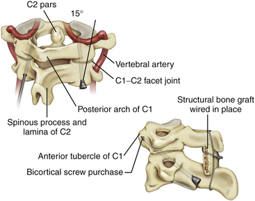
Transarticular C1–C2 screws as described by Magerl13 provide a very rigid and biomechanically sound construct with the incorporation of four cortical surfaces, but the insertion procedure is technically demanding because of the danger of vertebral artery injury especially in cases were atlantoaxial subluxation remains irreducible preoperatively. Although successful transarticular screw fixation of the atlantoaxial complex has been extensively reported in adult series, there have been only a handful of reports in the pediatric population. Analysis of clinical experience in the largest series of pediatric patients10,18,19 suggested a 4% rate of vertebral artery injury during screw placement; none of these injuries resulted in any long-term morbidity or mortality.
Because of the anatomical limitations complicating transarticular screw placement in adults and even more so in children, variations of C1–C2 screw fixation have been reported in adult patients in whom independent C1 lateral mass screws and C2 pars/pedicle screws were connected with either a plate11 or a rod.12 Atlantoaxial screw-rod fixation has been suggested as a safer procedure, and perhaps, as we have found, the technique is applicable in more patients despite anatomic variations, even in the smallest of pediatric patients. It is an ideal technique to fix and reduce occipitoatlantoaxial deformities that remain irreducible with closed reduction (Fig. 64-2).21,22
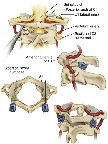
It is imperative that the entry point for the C1 lateral mass screw in the pediatric spine be placed at the confluence of the C1 lamina and the C1 lateral mass. The pediatric spine is unsuitable to accept a C1 lateral mass screw at alternative entry sites, such as the C1 lamina itself14 because of the high risk of violating the superior wall of the lamina and injuring the vertebral artery in the sulcus arteriosus.1
It is also important to note how the pediatric atlas differs from the adult atlas. In the adult atlas, the medial side of the C1 lamina is typically flush with the medial C1 lateral mass. However, in the pediatric atlas, the medial aspect of the C1 lamina is typically 2 to 3 mm laterally stepped-off from the medial surface of the C1 lateral mass. An entry point based on the medial aspect of the C1 lamina will place the entry of the C1 lateral mass screw dangerously lateral in extreme proximity to the vertebral artery. Instead, the medial surface of the C1 lateral mass itself must be used as a landmark for starting the C1 lateral mass screw23,24 (Fig. 64-3).
Although C1 lateral mass screw placement is still technically challenging and the potential risk of vertebral artery injury persists, our initial experience22 is that it is a feasible and efficacious part of an occipitocervical or atlantoaxial screw-rod construct in young patients.
C2 Pars/Pedicle and Translaminar Screws
C1–C2 transarticular screw placement is technically demanding because of the close proximity of the vertebral artery to the screw path. Vertebral artery injury has been reported to occur in 2% to 8% in several large series.25–27 Pars/pedicle screws may have a lower incidence of arterial injury,28 but these screws still place the vertebral artery and spinal cord at risk.29
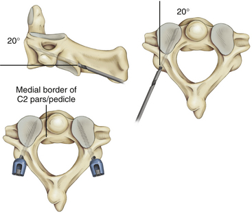
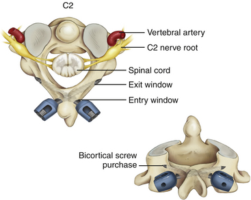
Wright30,31 described a new technique for rigid screw fixation of the axis involving the insertion of polyaxial screws into the laminae of C2 in a bilateral crossing fashion and their feasibility for placement in the general adult population. Because the C2 translaminar screws are not in proximity to the vertebral artery, this technique allows rigid fixation of C2 through a safer technique. Recently, teams of authors32,33 have reported their experience with this technique of crossing and noncrossing screws in small series of children (Fig. 64-4).
Subaxial Cervical Spine (C3–C7)
Lateral Mass Screws
Although lateral mass screw fixation in the cervical spine has been shown to provide excellent stability and high rates of fusion in adult patients,34–36 little has been published about the use of subaxial lateral mass screws in the pediatric age group. Unlike the adult age group, there is limited cadaveric biomechanical analyses of these types of constructs. In addition, based on comparative biomechanical studies of the cervical fixation procedures, there is not much difference in stability between lateral mass screw fixation and conventional nonscrew fixation methods, such as sublaminar wiring.37–41
The two most popular techniques for lateral mass screws are the Roy-Camille and the Magerl techniques. However, nerve roots, vertebral arteries, facet joints, and the dura and spinal cord are at risk during the placement of lateral mass screws. A recent review of the literature42 indicated that the youngest patient where subaxial lateral mass screws were successfully used was 8.2 years old. This correlates with the age at which most authorities agree that the developing spine takes on an “adult” configuration.43,44 Despite this, the authors were only able to place 3.5 × 10 mm screws — the shortest screw length that is manufactured. Although a solid fusion was achieved in this case after 3 months of rigid immobilization, another study36 of predominantly adult patients has suggested that a minimum subaxial lateral mass screw length of 14 mm is needed to confer any degree of biomechanical stability (Fig. 64-5).
Pedicle Screws
Pedicle screw fixation systems have been widely used for reconstruction of the thoracic and lumbar spine because of their biomechanical superiority. Abumi et al.45,46 reported clinical results of pedicle screw fixation for reconstruction of traumatic and nontraumatic lesions of the middle and lower cervical spine. However, the procedure in the upper cervical spine has been criticized due to the potentially high risk to neurovascular structures, except at the C2 level.47–49
Translaminar Screws
Recently, translaminar screws have been promoted as a safe alternative to pedicle screws in the axis and in the upper thoracic spine, as they decrease the risk of violation of the transverse foramen and vertebral artery injury in the cervical spine and the risk of damage to the spinal cord and exiting nerve roots in the upper thoracic spine50,51 without the need for image guidance. We now propose that translaminar screw fixation in the subaxial cervical spine is a consideration in highly selected cases, as an alternative to subaxial lateral mass screws in children with small lateral masses.
Potential drawbacks of this technique must also be noted. Although the dorsal laminar surface is exposed during surgery, the surgeon must be careful to avoid penetration of the nonvisualized ventral laminar wall because penetration could lead to damage to the thecal sac or spinal cord. A modification of Wright’s method of translaminar screw placement with an “exit” window in the dorsal lamina at the laminofacet line can help the surgeon avoid intracanicular violation of the translaminar screw.52 Preoperative fine-cut CT scans with axial, sagittal, and coronal views should be used to estimate the screw length and to determine if the subaxial lamina can accept a minimum 3.5-mm diameter screw. We suggest that the acceptable width of the lamina should be at least 4.0 mm. Clearly, translaminar screws should not be used without intact posterior elements.
Although the biomechanics of lateral mass screw fixation of the subaxial cervical spine are well described, there is no report comparing construct stability or screw pullout strength of translaminar and lateral mass screws in this region. CT morphometric analysis for axial and subaxial translaminar screw placement in the pediatric cervical spine shows the anatomy in 30.4% of patients younger than 16 years of age could accept bilateral C2 translaminar screws; however, the anatomy of the subaxial cervical spine only rarely could accept translaminar screws.53 Nonetheless, feasibility of translaminar screw placement in the subaxial cervical spine should be assessed on a case-by-case basis by careful study of preoperative thin-cut CT and sagittal and coronal reconstructions (Fig. 64-6).
Thoracic and Lumbar Spine
Wires, Hooks, and Pedicle Screws
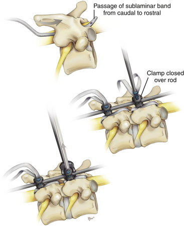
The history of spinal implants began in Kansas in 1887 when Dr. B.F. Wilkins reduced and fixed a T12–L1 dislocation with silver wires which he passed around the pedicles. Stainless steel wires were developed in the late 1930s. The surgical treatment of spinal deformity was transformed in the 1960s when the Harrington rod instrumentation system was introduced.54 The next major advance in spinal instrumentation came in 1982, when Luque rods and sublaminar wires were introduced. The Luque instrumentation system provided segmental correction and fixation, allowing a more rigid construct that avoided mandatory postoperative external immobilization.55
Related posts:
 Hearing Prosthetics: Surgical Techniques
 Surgical Management of Cerebrospinal Fluid Leakage after Spinal Surgery
 Atlantoaxial Instability and Stabilization
 Lumbar Spinal Arthroplasty: Clinical Experiences of Motion Preservation
 Arachnoid, Suprasellar, and Rathke’s Cleft Cysts
 Management of Skull Base Trauma
