Chapter 4 Cardiac Angiography
TECHNIQUES
Indications
In 1999, the Committee on Coronary Angiography of the American College of Cardiology and American Heart Association Task Force established guidelines for coronary angiography (Box 4-1). The final decision must ultimately be based on an analysis of the expected benefits of the procedure balanced against the risks of the technique. Patients who undergo cardiac surgery are usually catheterized first, although with evolving noninvasive techniques, some aspects of the catheterization may be modified or omitted. The clinical variables that can be determined by cardiac catheterization include coronary angiograms, measurement of chamber pressures, detection of intracardiac shunts, characterization of myocardial performance, quantification of valvular stenoses and regurgitation, and imaging of cardiac anatomy. When such information is essential for a management decision, a catheterization is warranted.
Box 4-1 American College of Cardiology and American Heart Association guidelines for coronary angiography
See Box 4-2 for relative contraindications to coronary angiography.
Box 4-2 Relative contraindications to coronary angiography
From Scanlon PJ, Faxon DP, Audet AM, et al.: ACC/AHA Guidelines for coronary angiography. A report of the American College of Cardiology/American Heart Association Task Force on practice guidelines (Committee on coronary angiography), J Am Coll Cardiol 33:1756-1824, 1999.
Catheterization Techniques
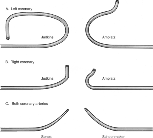
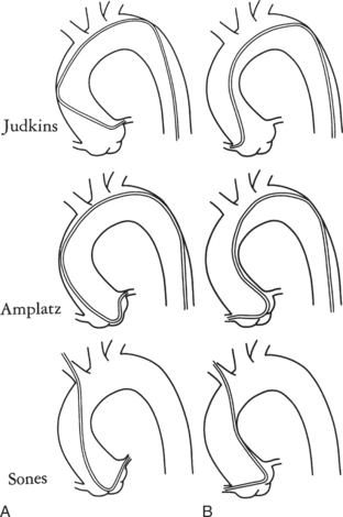
Ricketts and Abrams extended the concept of selective coronary catheterization by devising two catheters, one for each coronary artery, that could be introduced percutaneously into the femoral artery by the Seldinger technique. The concept of a preshaped catheter for selective catheterization was refined by Amplatz and others; various shapes were devised to surmount the difficulties of different aortic sizes and ectopic locations of coronary arteries (Fig. 4-1). In 1967 radiologist Melvin Judkins designed preshaped catheters for both the right and left coronary arteries. The left coronary catheter, if properly aligned, needed only to be advanced around a normal aortic arch to fall into the ostium; whereas the right coronary catheter needed a 180-degree twist after it had passed around the arch (Fig. 4-2). Different catheter shapes and other refinements were introduced by Bourassa and associates, Schoonmaker, and others.
Cineangiography
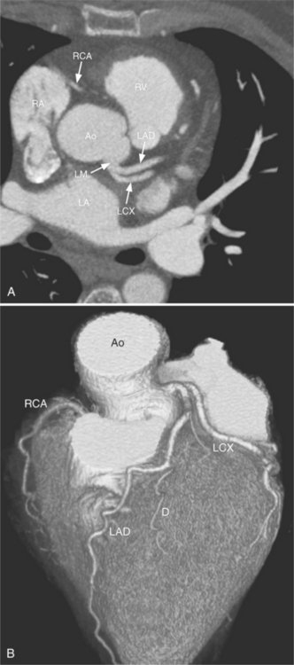
Despite years of development and improved acquisition techniques (gating with or without breath hold) magnetic resonance imaging (MRI) still cannot depict coronary arteries with results equivalent to angiography, even with blood pool contrast agent. Furthermore, MRI has limitations when cardiac patients, such as those with pacemakers, are imaged and this technique requires still, cooperative subjects. Recent developments with electrocardiography gated 64-detector row computed tomography (CT) units (Fig. 4-3) have provided higher resolution than MRI, but CT has its own limitations including the need for iodinated contrast, a high radiation dose, and a heart rate below 65 beats per minute.
Because coronary angiograms are obtained with digital imaging, immediate reviewing is possible during the procedure, which allows the operator to be confident or prompts him or her to obtain additional views.
Projection Positions
The catheter techniques, injection rates, and other technical factors are summarized in Tables 4-1 and 4-2. Power injection techniques are used for all types of cardiac angiography except for coronary arteriography, in which injection is carried out by hand. When high flow exists in the coronary arteries, as in arteriovenous fistulas and in aortic regurgitation, a power injection can be used safely with the same techniques used to inject small arteries in other parts of the body.
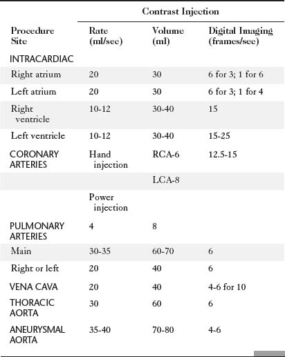
TABLE 4-2 Technical factors for thoracic angiography in children
| Contrast Injection | ||
|---|---|---|
| Procedure Site | Volume (ml/kg) | Delivery Time (sec) |
| INTRACARDIAC | 1-1.5 | 1-1.5 |
| Right atrium | ||
| Right ventricle | ||
| Left atrium | ||
| Left ventricle | ||
| PULMONARY ARTERY | 2 | 1.5 |
| THORACIC AORTA | 2 | 1.5 |
Volume is adjusted to the size of the vascular bed and flow through it.
Delivery time is roughly that of two heartbeats (e.g., at heart rate of 120 beats per sec, inject contrast over 1 sec).
Absolute maximum contrast dose is 5 milliliters per kilogram per day adjusted downward if renal function is decreased and if baby is less than 1 month old.
Radiation Exposure and Protection
The hazards of ionizing radiation are well known to radiologists and should be understood by all physicians who use x-ray equipment. Guidelines for maximum yearly occupational exposure have been established by the National Council on Radiation Protection (NCRP; Table 4-3). The NCRP is considering lowering the total body limit to 20 mSv annually. Lead eyeglasses and thyroid shielding help to diminish the dose received by the angiographer. The effective dose for a physician wearing a lead apron and thyroid shield is about 1.7 mSv/year, rising to 3.5 mSv/year without the thyroid shield. The average effective dose per application, for all types of procedures, is around 1 to 2 μSv for the physician when fully protected.
| OCCUPATIONAL EXPOSURE FOR PEOPLE WORKING WITH RADIATION | |
| Annual | 20 mSv/year over 5 years (ICRP) or 50 mSv/year (NCRP) |
| Cumulative | 10 mSv (1 rem) × age |
| PUBLIC EXPOSURE | |
| Annual | 1 mSv/year over 5 years (100 mrem) (ICRP and NCRP) |
| Lens of eye | 15 mSv (1.5 rem) |
| Skin | 50 mSv (5 rem) |
| Embryo/fetus during gestation | 0.5 mSv (50 mrem) |
Note: Average annual background radiation from natural sources: 3 mSv (300 mrem).
ICRP, International Council on Radiation Protection; NCRP, National Council on Radiation Protection and Measurements.
Adapted with permission from National Council on Radiation Protection and Measurements, Limitation of exposure to ionizing radiation, Report No 116, Bethesda, MD, 1993, National Council on Radiation Protection and Measurements.
Operator radiation exposure during interventional procedures is much higher than for diagnostic angiography. Mikalason and colleagues surveyed interventional angiographers from 17 institutions and calculated a mean annual effective dose to the angiographer of 0.3 to 1 rem (3 to 10 mSv). Dash and colleagues found that during percutaneous angioplasty, operator radiation exposure is nearly doubled compared to routine coronary angiography.
Radiation exposure to the patient undergoing cardiac catheterization is higher than for any other type of radiologic examination but has been justified because the information gained is considered to be necessary for clinical management (Table 4-4). Repeated catheterization, particularly in critically ill children, may give a large radiation dose over a relatively short time span.
TABLE 4-4 Summary of mean radiation exposure during cardiac catheterization to patient and physician
| Mean Dose (mrem) | ||
|---|---|---|
| Site | Patient | Physician |
| ADULTS | ||
| Eye | — | 20 |
| Thyroid | 250 | 16 |
| Chest | 1,100 | 500 |
| Chest (inside apron) | — | 50 |
| Hand | — | 1-30 |
| Gonads | 12 | <10 |
| Skin (direct beam) | 25,000-50,000 (25-50R) | |
| CHILDREN | ||
| Eye | 25 | |
| Thyroid | 430 | |
| Chest | 7,500 | |
| Abdomen | 150 | |
| Gonads | 10 | |
| COMPARISON EXPOSURES | ||
| 1-year cumulative background from natural sources | 100 | |
| Chest radiograph | 10 | |
| Upper gastrointestinal | 3000 series | |
| Lumbar spine series | 3000 | |
| Pulmonary angiography | 15,000 | |
| Chest fluoroscopy | 1-2 rad/min | |
Reprinted with permission of American Journal of Cardiology from Miller SW, Castronovo FP Jr: Radiation exposure and protection in cardiac catheterization laboratories, Am J Cardiol 55:171–176, 1985. Copyright © 1985 by Excerpta Medica, Inc.
Additional local lead shielding should be considered to help limit scattered radiation. The smallest x-ray beam possible will help to reduce the exposure of both the patient and the operator. Movable shields or drapes are available for most of the current angiographic units. Side drapes between the patient and the operator reduce scatter passing through the patient that would ordinarily be received by the operator. Cranial and caudal angulations considerably increase the x-ray tube output, the radiation received by the patient, and the secondary scatter received by the angiographer.
Because radiation decreases as the square of the distance, all personnel who are not needed in the room should be located elsewhere. For instance, the electrophysiologic data collection can be performed from a remote location rather than from beside the fluoroscopy table. Those nurses and technicians remaining in the room should stay as far as practical from the x-ray tube. The radiation physicist can monitor the radiation burden, evaluate the fluoroscopy techniques for each angiographer, and periodically measure the radiation output at various places in the room.
Table 4-5 compares the radiation dose of coronary angiography with other radiology examinations.
TABLE 4-5 Typical effective dose values for radiology examinations
| Imaging Examination | Typical Effective Dose Values (mSv) |
|---|---|
| Dental bite wing radiography | <0.1 |
| Chest radiography | 0.1-0.2 |
| Mammography | 0.3-0.6 |
| Lumbar spine radiography | 0.5-1.5 |
| Barium enema | 3-6 |
| Sestamibi myocardial perfusion study | 13-16 |
| Head CT | 1-2 |
| Chest CT | 5-7 |
| Abdominal CT | 5-7 |
| Coronary artery calcium CT | 1-3 |


